Projector
a projector and projection image technology, applied in the field of projectors, can solve the problems of difficult to further brighten the projection image, difficult to stabilize and concentrated thermal load on the single solid-state light source device, and achieve the effect of brightening the projection image and stabilizing the color balance of the projection imag
- Summary
- Abstract
- Description
- Claims
- Application Information
AI Technical Summary
Benefits of technology
Problems solved by technology
Method used
Image

Examples
first embodiment
[0072]First, the configuration of a projector 1000 according to a first embodiment will be described.
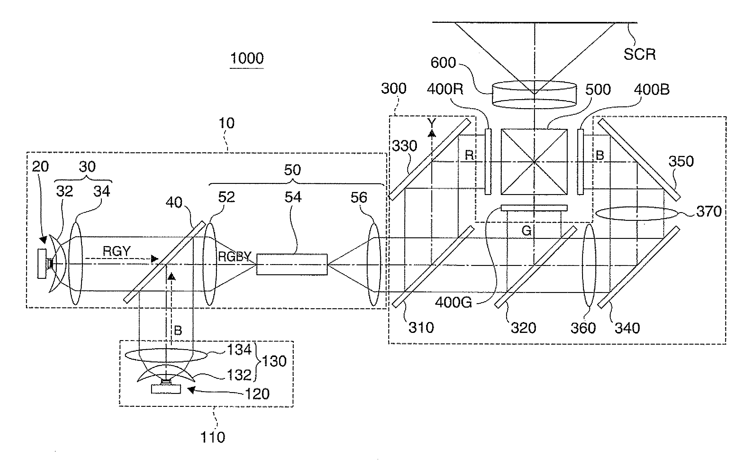
[0073]FIG. 1 is a plan view showing optical systems of a projector 1000 according to a first embodiment.
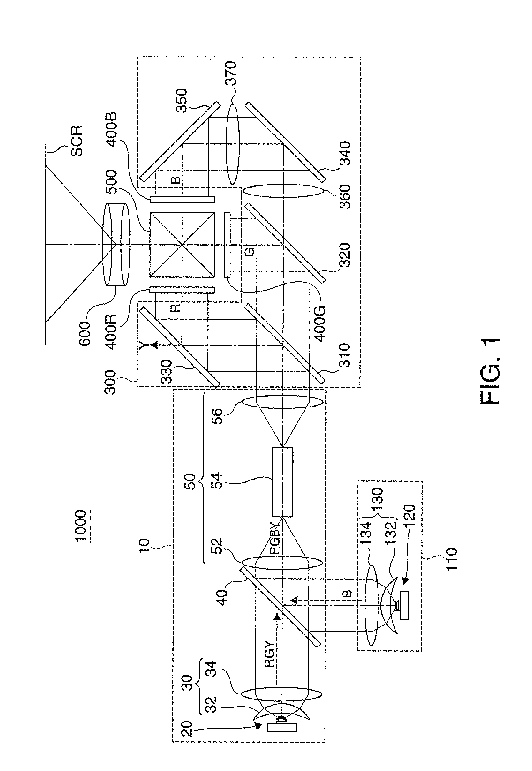
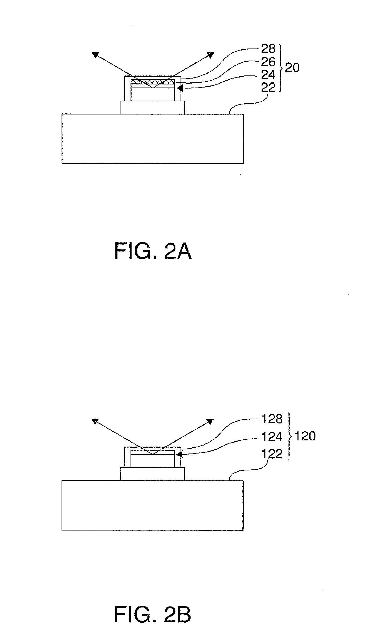
[0074]FIGS. 2A and 2B are diagrams illustrating a first solid-state light source device 20 and a second solid-state light source device 120 in the projector 1000 according to the first embodiment. FIG. 2A is a sectional view of the first solid-state light source device 20. FIG. 2B is a sectional view of the second solid-state light source device 120.
[0075]FIGS. 3A to 3C are graphs showing relative light-emission intensity of a first solid-state light source 24, a fluorescent layer 26, and a second solid-state light source 124 in the projector 1000 according to the first embodiment. FIG. 3A is a graph showing relative light-emission intensity of a first solid-state light source 24. FIG. 3B is a graph showing relative light-emission intensity of a fluorescent layer 26. FIG. 3C is a g...
second embodiment
[0120]FIG. 4 is a plan view showing optical systems of a projector 1002 according to a second embodiment.
[0121]The projector 1002 of the second embodiment basically has the same configuration as the projector 1000 of the first embodiment, but a first illumination device has the configuration different from that in the projector 1000 of the first embodiment.
[0122]That is, in the projector 1002 of the second embodiment, as shown in FIG. 4, a first illumination device 12 further includes an excitation light reflecting mirror 60 which is located at the back of the collimation optical system 30 to directly transmit light (red light component, yellow light component, and green light component), which is converted by the fluorescent layer and emitted from the fluorescent layer 26, and to reflect excitation light (blue light component), which is emitted while being not converted by the fluorescent layer 26, toward the fluorescent layer 26.
[0123]As described above, in the projector 1002 of t...
third embodiment
[0127]FIG. 5 is a plan view showing optical systems of a projector 1004 according to a third embodiment.
[0128]The projector 1004 of the third embodiment basically has the same configuration as the projector 1000 of the first embodiment, but a first illumination device has the configuration different from that in the projector 1000 of the first embodiment.
[0129]That is, in the projector 1004 of the third embodiment, as shown in FIG. 5, a first illumination device 14 includes a lens integrator optical system 70, instead of the rod integrator optical system 50. The lens integrator optical system 70 includes a first lens array 72, a second lens array 74, and a superimposing lens 76.
[0130]As described above, in the projector 1004 of the third embodiment, the first illumination device has the configuration different from that in the projector 1000 of the first embodiment; however, the two color light components (red light component and green light component) emitted from the first solid-s...
PUM
 Abstract
Description
Claims
Application Information
 - R&D
- Intellectual Property
- Life Sciences
- Materials
- Tech Scout
- Unparalleled Data Quality
- Higher Quality Content
- 60% Fewer Hallucinations
Browse by: Latest US Patents, China's latest patents, Technical Efficacy Thesaurus, Application Domain, Technology Topic, Popular Technical Reports.
© 2025 PatSnap. All rights reserved.Legal|Privacy policy|Modern Slavery Act Transparency Statement|Sitemap|About US| Contact US: help@patsnap.com