Pattern generation systems and high bandwidth focus control system with suppressed reaction forces and noise

Active Publication Date: 2011-03-03
MICRONIC LASER SYST AB
View PDF19 Cites 24 Cited by
  • Summary
  • Abstract
  • Description
  • Claims
  • Application Information

AI Technical Summary

Benefits of technology

[0027]The focus motor may further include: a hose connected to the counterweight. The hose may be configured to cool the focus motor by vacuum suction. A soft hose may be connected to the counterweight and configured to supply air to the counterweight. A damper ring may be mounted on the counterweight and configured to suppress damage caused by collisions between the c

Problems solved by technology

A potential problem with pattern generation systems having movable scanning heads is that the scanning head may need services such as cooling water, gas and/or radio frequency (RF) cables.
The bending of the cables may also negatively affect reliability and/or performance of the system.
Likewise, many related art pattern generation systems are relatively heavy, bulky and/or otherwise unsuitable for relati

Method used


Image

  • Pattern generation systems and high bandwidth focus control system with suppressed reaction forces and noise
  • Pattern generation systems and high bandwidth focus control system with suppressed reaction forces and noise
  • Pattern generation systems and high bandwidth focus control system with suppressed reaction forces and noise

Examples


Embodiment Construction

[0046]Example embodiments will now be described more fully with reference to the accompanying drawings, in which some example embodiments are shown. In the drawings, the thicknesses of layers and regions are exaggerated for clarity. Like reference numerals in the drawings denote like elements.

[0047]Detailed illustrative embodiments are disclosed herein. However, specific structural and functional details disclosed herein are merely representative for purposes of describing example embodiments. Example embodiments may, however, may be embodied in many alternate forms and should not be construed as limited to only the example embodiments set forth herein.

[0048]It should be understood, however, that there is no intent to limit scope to the particular example embodiments disclosed. On the contrary example embodiments are to cover all modifications, equivalents, and alternatives falling within the scope. Like numbers refer to like elements throughout the description of the figures.

[0049]...


PUM


Abstract

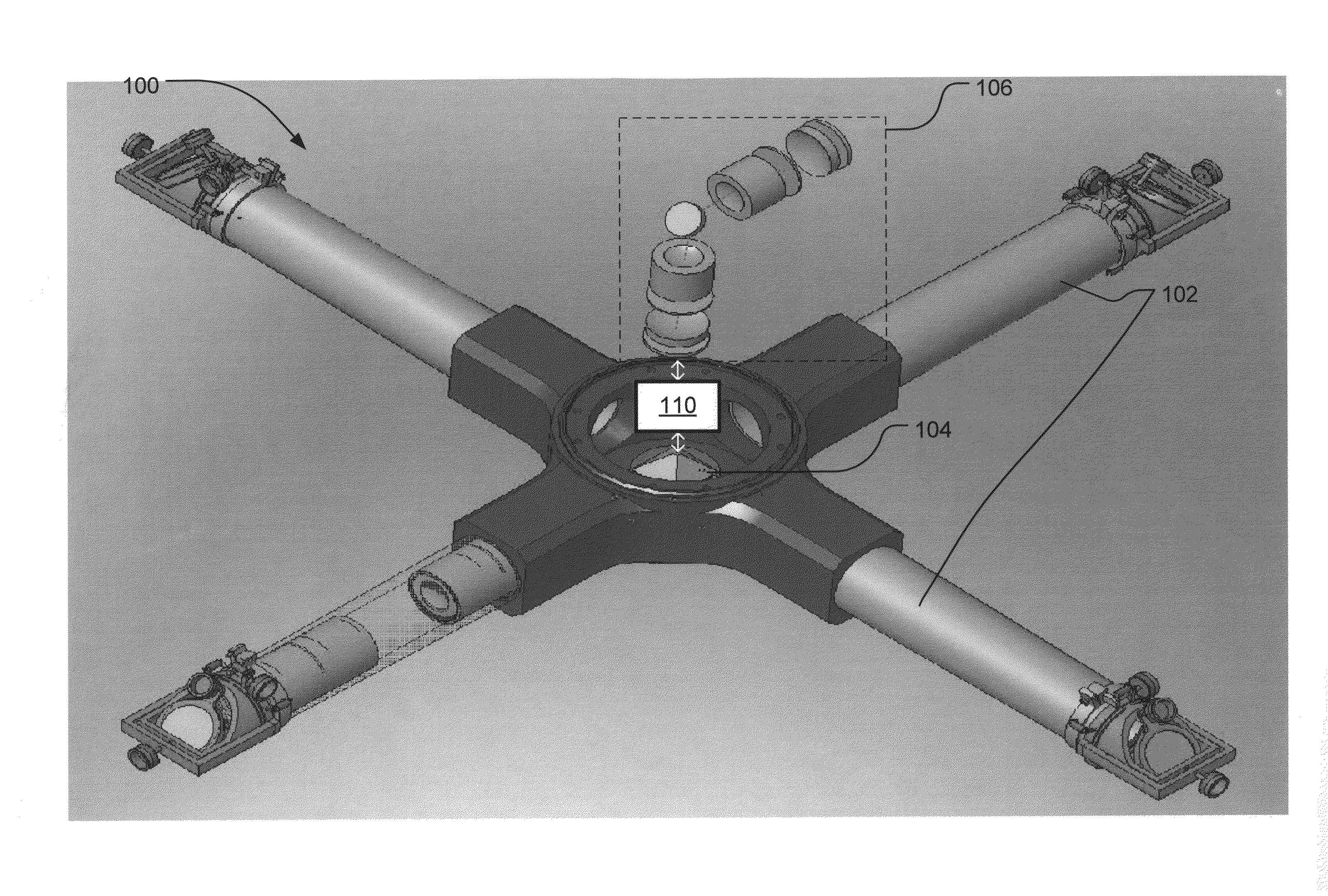
A pattern generation system includes an optical system and a rotor. The optical system is configured to project a laser image onto an optical scanner. The rotor has a plurality of optical arms arranged at a first angle relative to one another, and further includes the optical scanner. The laser image is sequentially reflected by the optical scanner into each of the plurality of optical arms of the rotor to generate a pattern on a workpiece.

Description

CROSS-REFERENCE TO RELATED APPLICATION(S)[0001]This non-provisional U.S. patent application claims priority under 35 U.S.C. §119(e) to provisional U.S. patent application No. 61 / 272,206, filed on Sep. 1, 2009, the entire contents of which are incorporated herein by reference.TECHNICAL FIELD[0002]Example embodiments relate to pattern generators, pattern generation systems, tools, focus control systems, methods, apparatuses and systems for scanning of workpieces and / or substrates (e.g., relatively large flat substrates for reading and writing patterns or images).BACKGROUNDDescription of the Related Art[0003]In some related art pattern generation systems, a stage advances a workpiece in one direction, while a head scans the workpiece in a perpendicular direction. Pattern generation systems having a stationary workpiece and an x-y-movable scanning head, or a stationary head and an x-y-movable stage are also known.[0004]A potential problem with pattern generation systems having movable s...

Claims


Application Information

Patent Timeline
IPC IPC(8): G02B26/08
CPCG03F7/70366G03F7/709G03F7/70766G03F7/2055
Inventor WALTHER, JONASHEDEVAM, TORBJOM
Owner MICRONIC LASER SYST AB
Why Eureka
Try Eureka