Microscope with retain focus control

a technology of focus control and microscope, which is applied in the direction of controllers with continuous output signals, cameras, instruments, etc., can solve the problems of affecting the electromechanical components of the motion unit, the inability to conduct long-term time series experiments, and so as to reduce the stress on the motion unit

Active Publication Date: 2011-03-03
CARL ZEISS MICROSCOPY GMBH
View PDF6 Cites 9 Cited by
  • Summary
  • Abstract
  • Description
  • Claims
  • Application Information

AI Technical Summary

Benefits of technology

[0006]Based on the aforementioned, the invention further develops a microscope of the in

Problems solved by technology

Such periods of time are, for example, necessary for experiments with live cells, when regulating the incubation or the ambient temperature is often critical and deviations from the focal position (i.e., drifts in the observational direction of the imaging optics) would disrupt or make impossible long-term time series experiments.
Als

Method used


Image

  • Microscope with retain focus control
  • Microscope with retain focus control

Examples


Embodiment Construction

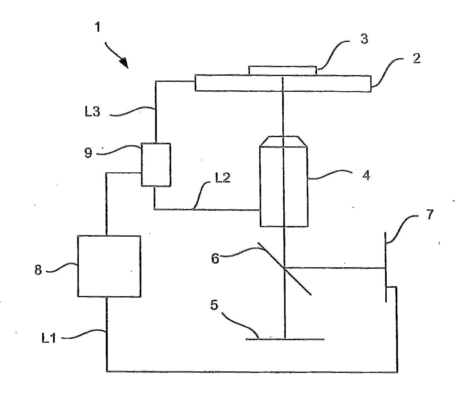
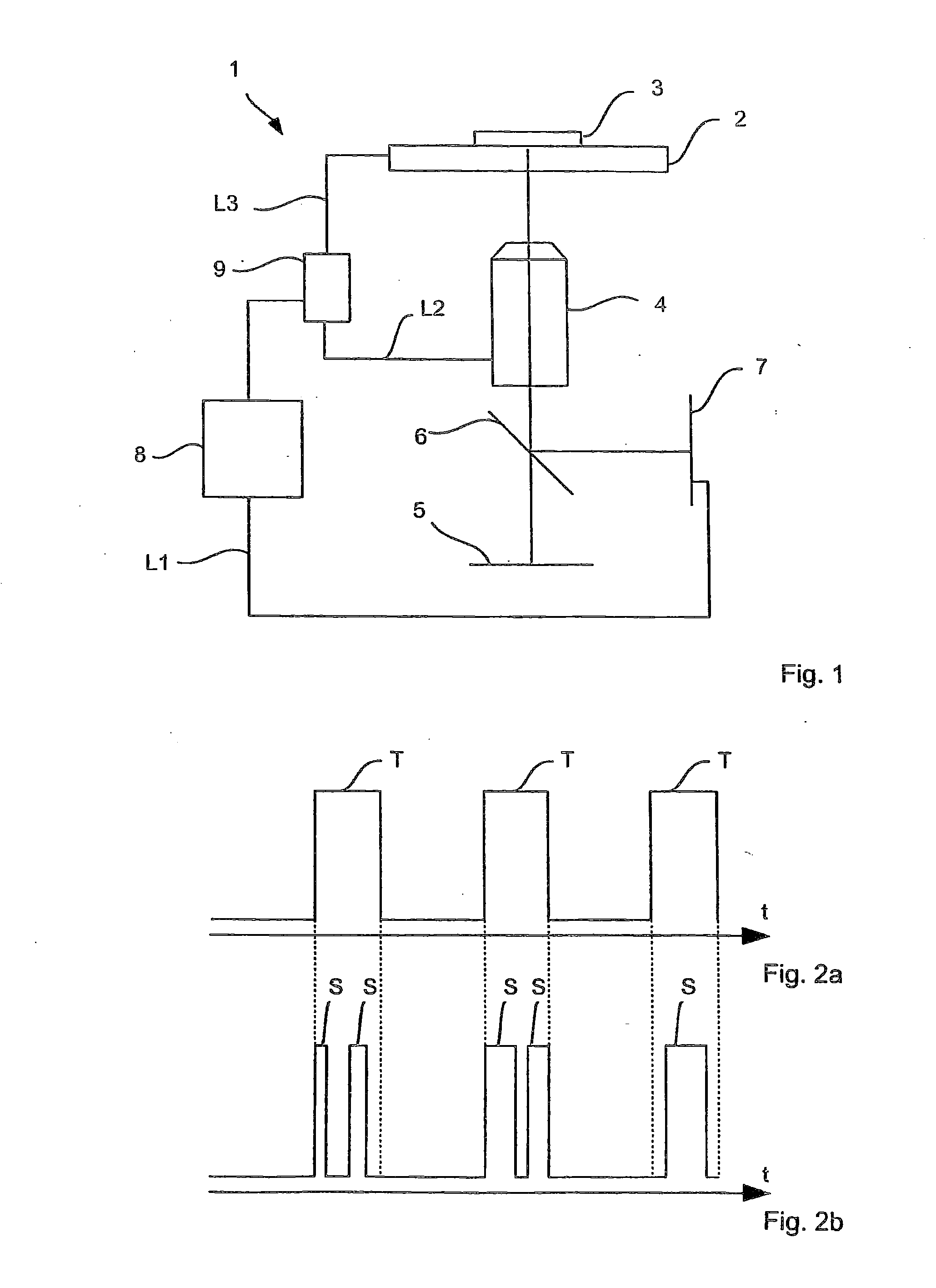
[0038]The embodiment in FIG. 1 comprises the microscope 1, according to the invention, which is, for example, designed as an inverted microscope, a stage 2 that holds a sample 3 to be examined, and imaging optics 4 which map the sample to be examined onto a detector (for example, a CCD detector) of a detector unit 5.

[0039]Furthermore, the microscope comprises a beam splitter 6 which allows the radiation for the mapping of sample 3 onto the detector of the detector unit 5 to pass almost unaltered and guides the focus measurement radiation (e.g., infrared radiation) onto the focus measurement unit 7. The focus measurement radiation is produced, e.g., with a radiation source (not shown), arranged in the area of the focus measurement unit, mapped via the mirror 6 and imaging optics 4 onto the sample 3, reflected from the sample 3 and directed via imaging optics 4 and the mirror 6, as already mentioned, onto the focus measurement unit 7. The focus measurement unit 7 can measure the actua...


PUM


Abstract

A microscope including an imaging optical unit, a sample stage for supporting a sample to be examined, a movement unit, by which the distance between sample stage and imaging optical unit can be altered, a focus measuring unit, which measures the present focus position and outputs a focus measurement signal, a control unit for maintaining a predetermined focus position for examinations of the sample that are separated from one another in time. The control unit receives the focus measurement signal and derives a deviation of the present focus position from the predetermined focus position. Dependent on the deviation derived the movement unit, changes the distance between sample stage and imaging optical unit so that the predetermined focus position is maintained. The control unit drives the movement unit (9) for maintaining the predetermined focus position only before and/or after at least one of the examinations, but never during the examinations.

Description

PRIORITY CLAIM[0001]The present application is a National Phase entry of PCT Application No. PCT / EP2009 / 002502, filed Apr. 4, 2009, which claims priority from German Application Number 102008018864.6, filed Apr. 15, 2008, the disclosures of which are hereby incorporated by reference herein in their entirety.FIELD OF THE INVENTION[0002]The invention relates to a microscope with imaging optics, a stage for supporting a sample to be examined, a motion unit for adjusting the distance between stage and imaging optics, a focus measurement unit which measures the actual focal position and emits a focus measurement signal, and a control unit for retaining a predetermined focal position for temporally spaced examinations of the sample, whereby the control unit thereto receives the focus measurement signal and derives there from a deviation between the actual focal position and the predetermined focal position, and depending on the derived deviation, changes the distance between the stage and...

Claims


Application Information

Patent Timeline
IPC IPC(8): G02B21/26G02B21/00
CPCG02B21/367G02B21/241G03B13/34G01B11/22G03B13/32G01B11/285G05B11/12G05B11/06G01B11/28G05B11/10G03B13/36G06V20/69
Inventor STEINBORN, STEFANWEHNER, EUGENMITZKUS, REINERMILINOVICI, GLEBLEIDENBACH, STEFFENWESTPHAL, PETER
Owner CARL ZEISS MICROSCOPY GMBH
Why Eureka
Try Eureka