Plasma display device

a technology of display device and plasma, which is applied in the direction of television system, electrical apparatus casing/cabinet/drawer, instruments, etc., can solve the problem of not allowing enough internal heat to be emitted, and achieve the effect of discharging the heat of the circuit board and emitted enough internal hea

Inactive Publication Date: 2011-03-03
PANASONIC CORP
View PDF13 Cites 32 Cited by
  • Summary
  • Abstract
  • Description
  • Claims
  • Application Information

AI Technical Summary

Benefits of technology

[0011]According to the above-mentioned configuration, the circuit boards are arranged concentrically, and these circuit boards are accommodated in the projecting portion of the back cover. Therefore, it is possible to ensure a space facing the edge portion of the back cover in the periphery of the projecting portion of the back cover. Since the projecting portion of the back cover is provided with the air inlets and the air outlets on its peripheral wall, even when the plasma display device is mounted on the wall or placed near the wall so that the main wall of the projecting portion is close to or in contact with the wall surface, it is possible to use the thus ensured space facing the edge portion of the back cover as a path for dissipating the heat of the circuit boards by the fan. Further, the heat from the PDP transferred through the chassis is released into the atmosphere by radiation through the edge portion of the back cover. Thus, the plasma display device of the present invention can emit internal heat sufficiently, even when being mounted on the wall or placed near the wall.

Problems solved by technology

However, the configuration indicated in FIG. 7 does not allow the internal heat to be emitted sufficiently when the plasma display device 101 is mounted on the wall or placed near the wall, because the airflow into the air inlet 111 and the airflow from the air outlet 110 are hampered by the wall surface being close to or in contact with the back cover 107.

Method used


Image

  • Plasma display device
  • Plasma display device
  • Plasma display device

Examples


first embodiment

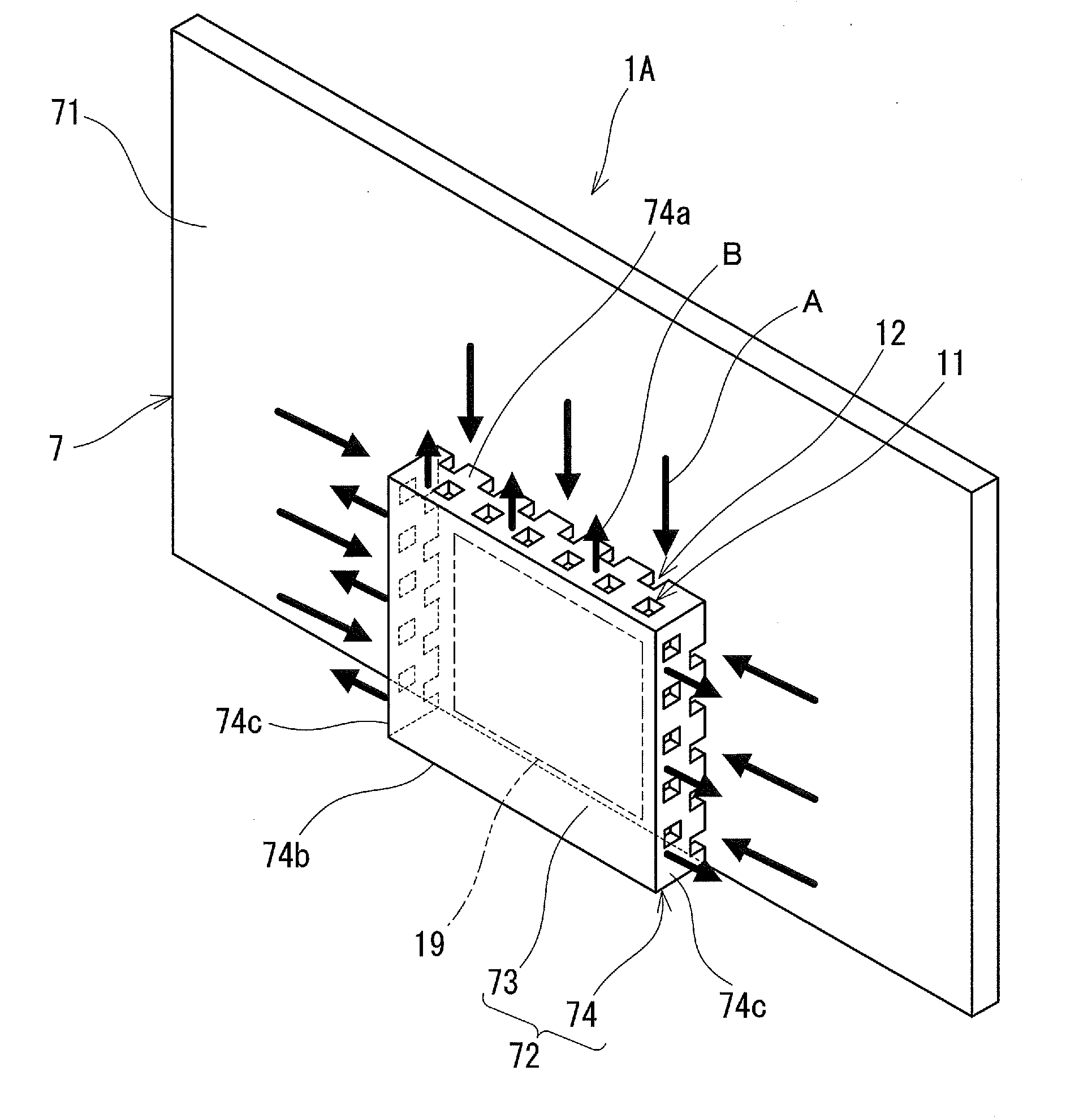
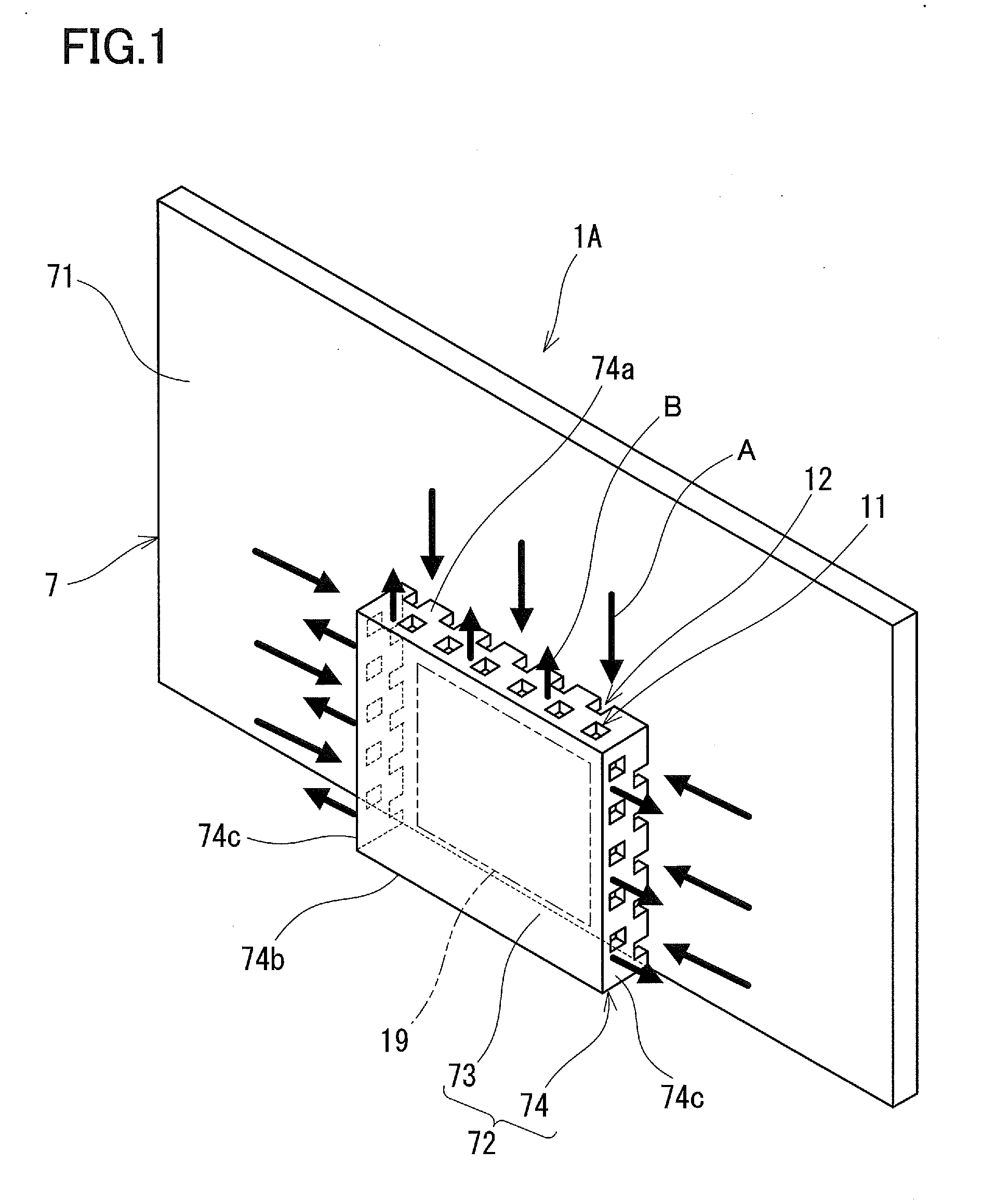
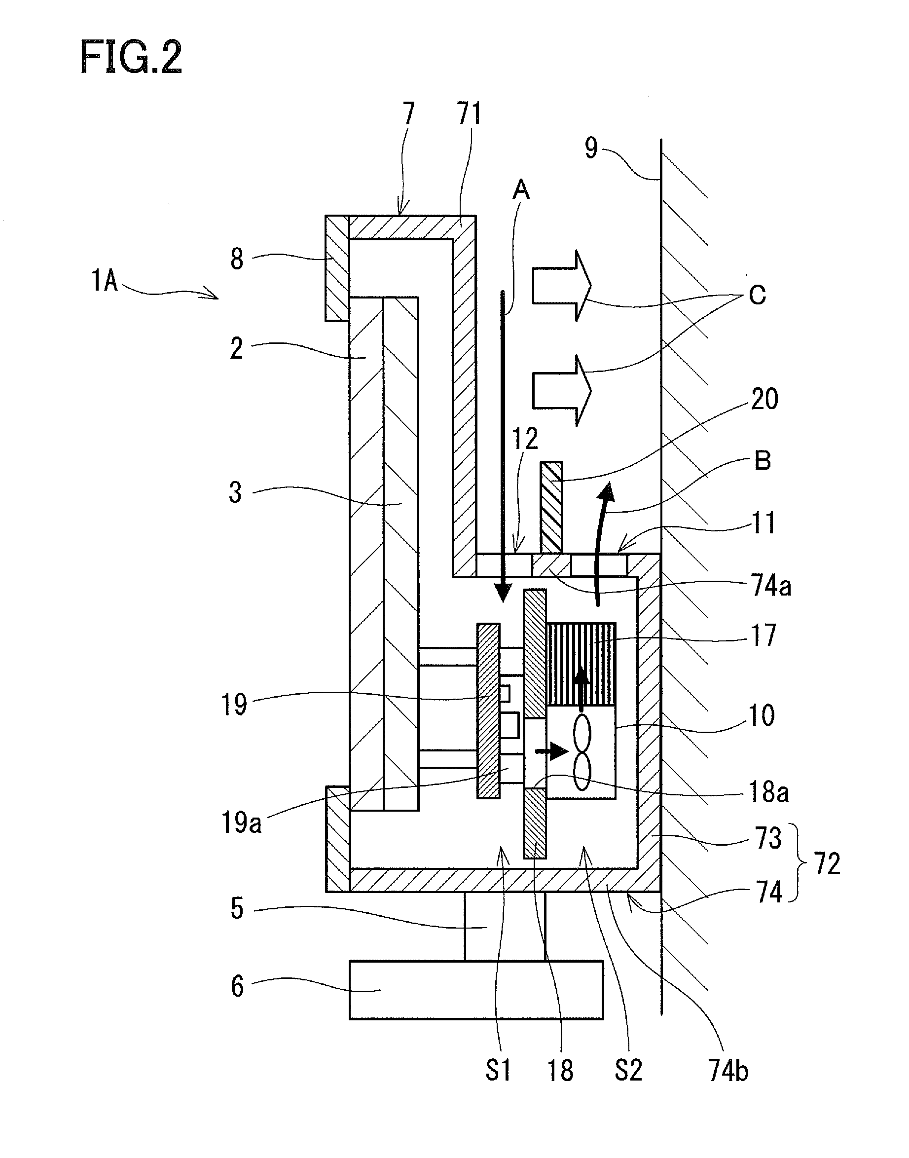
[0020]FIG. 1 and FIG. 2 indicate a plasma display device 1A according to the first embodiment of the present invention. The plasma display device 1A is provided with a PDP 2 for displaying images, a chassis 3 supporting the PDP 2 on its front surface, and a plurality of circuit boards 19 for driving the PDP 2 that are arranged on the back side of the chassis 3. It should be noted that the plurality of the circuit boards 19 are illustrated as a single board to simplify the view in FIG. 1. Further, the plasma display device 1A is provided with a front cover 8 and a back cover 7 that constitute a housing. The housing accommodates the PDP 2, the chassis 3 and the circuit boards 19.

[0021]The PDP 2 has an elongated shape and is placed in an upright position using a base 6 for installation that has a support portion 5 so that the longitudinal direction coincides with the substantially horizontal direction and the short direction coincides with the substantially vertical direction, in this ...

second embodiment

[0047]FIG. 3 and FIG. 4 indicate a plasma display device 1B according to the second embodiment of the present invention. It should be noted that the same parts as in the first embodiment may be indicated with identical reference numerals and the descriptions thereof are omitted in this embodiment. Further, in order to make it easy to understand the features of the second embodiment, the illustrations of the air inlets 12 and the air outlets 11 are omitted in FIG. 4. However, the configurations of the air inlets 12 and the air outlets 11 that have been described in the first embodiment and its modified embodiment also can be applied to this embodiment.

[0048]In this embodiment, a separation wall 15 that separates the space interposed between the chassis 3 and the circuit boards 19 into the space on the chassis 3 side and the space on the circuit boards 19 side is provided. The circuit boards 19 are mounted to the separation wall 15 via bosses.

[0049]It is preferable that the separation...

modified embodiment

[0059]It should be noted that although the heat pipes 16 are in contact also with the back surface of the chassis 3 in the embodiment, they may be spaced apart therefrom. However, even if the separation wall 15 is provided, the temperature of the portion facing the circuit boards 19 in the chassis 3 tends to be high. Therefore, it is preferable that the heat pipes 16 be in contact with the back surface of the chassis 3 as is the case of the above-mentioned embodiment. Such a configuration allows the heat pipes 16 to release the heat efficiently to the edge portion 71 of the back cover 7 from the portion in the chassis 3 where the temperature tends to be high, thus suppressing the increase in temperature of the portion in the chassis 3 where temperature tends to be high.

[0060]Further, the heat pipes 16 are not necessarily arranged in a radial pattern that spreads out from the separation wall 15, and may be arranged so that identical V shapes are formed in multiple steps, for example ...


PUM


Abstract

A plasma display device is provided with a chassis supporting a PDP on its front surface, circuit boards located within a specific region of the back surface of the chassis, a back cover including an edge portion covering the outside of the specific region of the back surface of the chassis and a projecting portion accommodating the plurality of the circuit boards, and a fan arranged inside a space defined by the projecting portion. The peripheral wall of the projecting portion is provided with a plurality of air inlets and a plurality of air outlets.

Description

BACKGROUND OF THE INVENTION[0001]1. Field of the Invention[0002]The present invention relates to a plasma display device that uses a plasma display panel as a display device.[0003]2. Description of Related Art[0004]In recent years, thin display devices have spread rapidly. Such thin display devices are expected to spread more and more in the future and to replace conventional CRTs. Currently, thin display devices usually are placed on the floor as are conventional CRTs. However, in the future, wall-mounted or near-wall installation will become mainstream to take more advantage of the space saving features of the thin display devices.[0005]Meanwhile, in some conventional plasma display devices, as one of the thin display devices, an air inlet and air outlet are provided on a back cover, and internal heat is emitted to the outside by forced convection (ventilation) using a fan. Further, others emit internal heat to the outside by natural convection (ventilation) without a fan.[0006]Fo...

Claims


Application Information

Patent Timeline
Patent Type & Authority Applications(United States)
IPC IPC(8): H05K7/20
CPCH05K7/20972H05K7/2099
Inventor TAKAHARA, ICHIRO
Owner PANASONIC CORP
Why Eureka
Try Eureka