Thermoacoustic device with heat dissipating structure

a thermoacoustic device and structure technology, applied in indirect heat exchangers, air heaters, lighting and heating apparatuses, etc., can solve the problems of large specific surface area of carbon nanotube film used in thermoacoustic devices, extremely weak sound of thermophones adopting platinum strips, and extremely small heat capacity per unit area

Active Publication Date: 2011-03-03
TSINGHUA UNIV +1
View PDF100 Cites 30 Cited by
  • Summary
  • Abstract
  • Description
  • Claims
  • Application Information

AI Technical Summary

Benefits of technology

[0007]Thermoacoustic effect is the conversion of heat to acoustic signals. When signals are inputted into a thermoacoustic element, heating is produced in the thermoacoustic element according to the variations of the signal and / or signal strength. Heat is propagated into the surrounding medium. The heating of the medium causes thermal expansion and produces pressure waves in the surrounding medium, resulting in sound wave generation. Such an acoustic effect induced by temperature waves is commonly called “the thermoacoustic effect”.

Problems solved by technology

However, these types use mechanical vibration to produce sound waves by “electro-mechanical-acoustic” conversion.
The heating of the medium causes thermal expansion and produces pressure waves in the surrounding medium, resulting in sound wave generation.
The heat capacity per unit area of the platinum strip with the thickness of 7×10⁻⁵ cm is 2×10⁻⁴ J / cm2*K. However, the thermophone adopting the platinum strip produces extremely weak sound.
The carbon nanotube film used in the thermoacoustic device has a large specific surface area, and extremely small heat capacity per unit area.
However, during operation, the carbon nanotube film will eventually generate heat stored in the base, which may scald a user's hand or may burn anything near the base.
The performance of the thermoacoustic device will be adversely affected.

Method used


Image

  • Thermoacoustic device with heat dissipating structure
  • Thermoacoustic device with heat dissipating structure
  • Thermoacoustic device with heat dissipating structure

Examples


Embodiment Construction

[0024]The disclosure is illustrated by way of example and not by way of limitation in the figures of the accompanying drawings in which like references indicate similar elements. It should be noted that references to “an” or “one” embodiment in this disclosure are not necessarily to the same embodiment, and such references mean at least one.

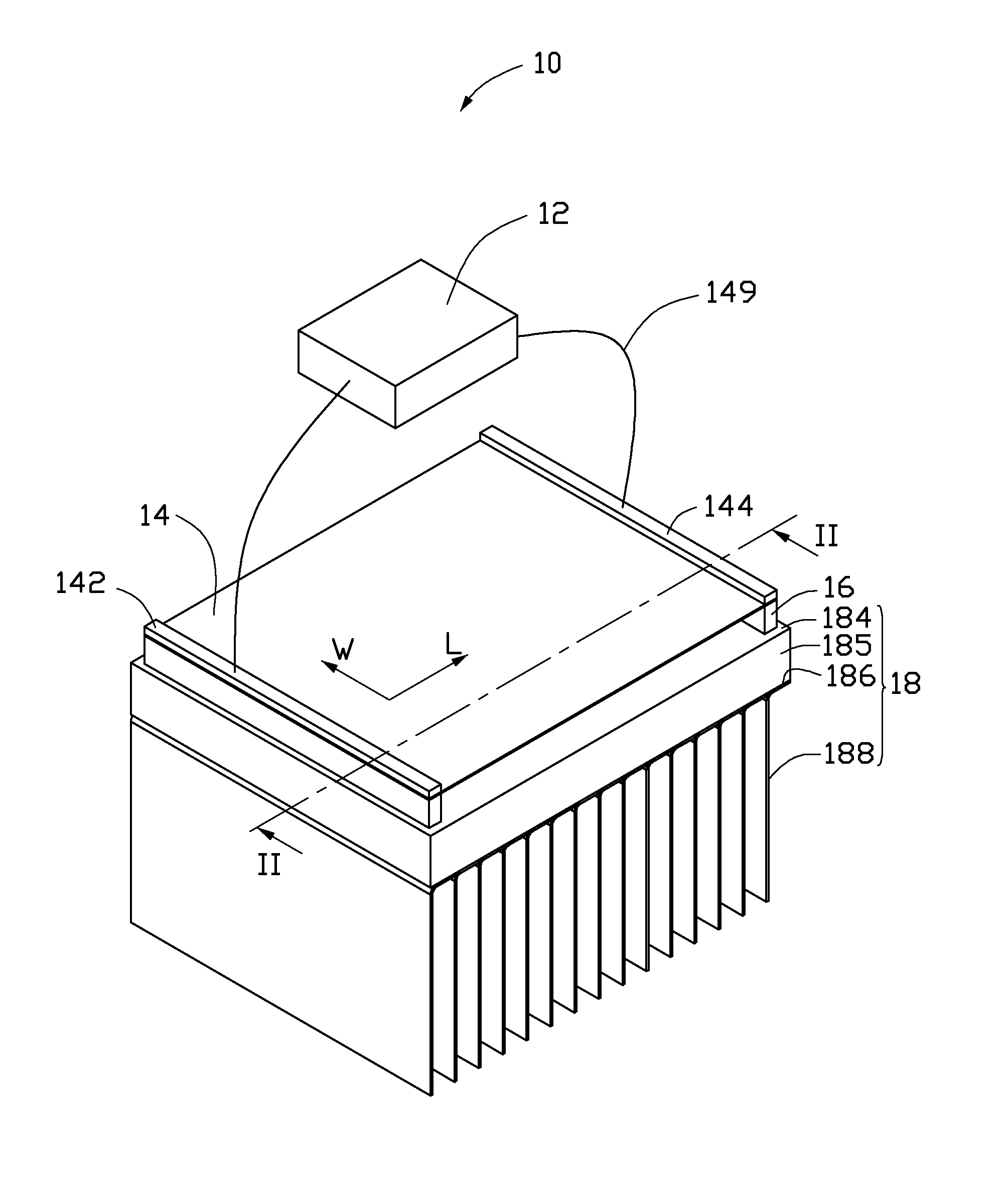
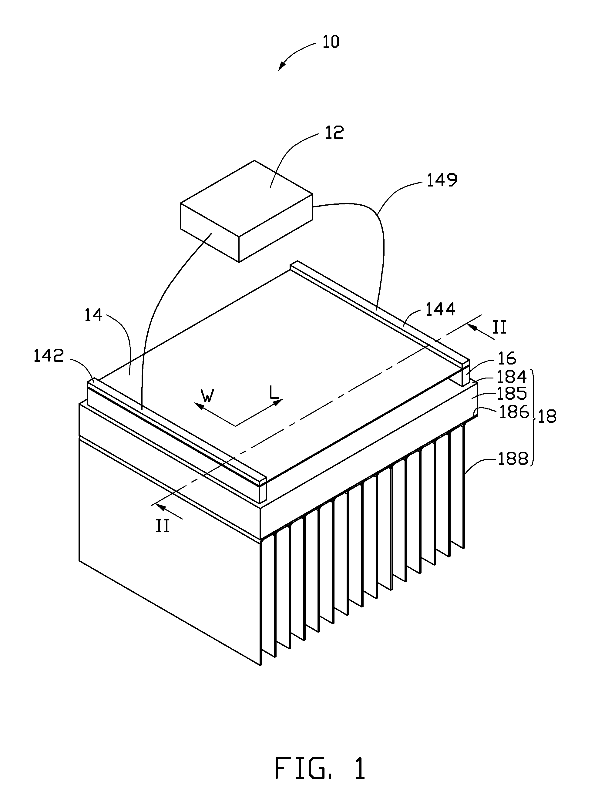
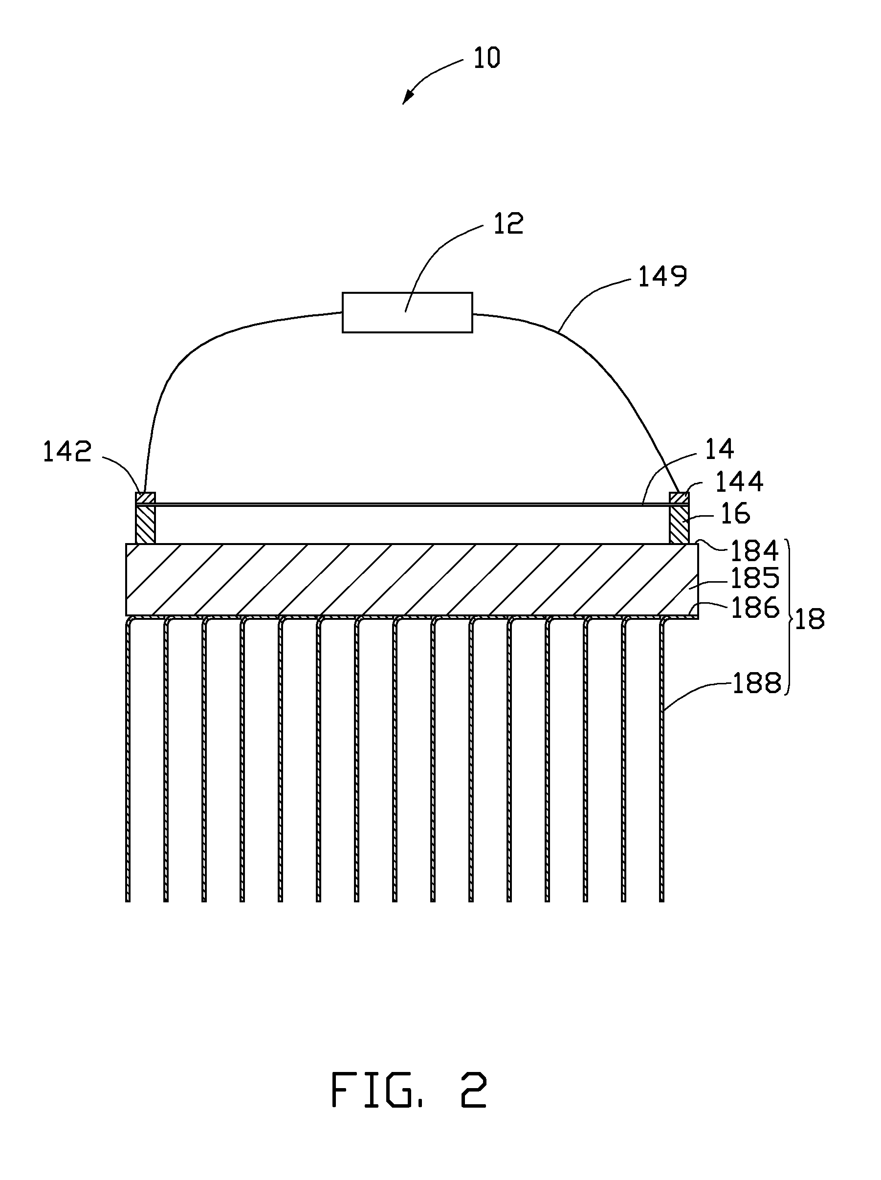
[0025]One embodiment of a thermoacoustic device 10 is illustrated in FIGS. 1-2. The thermoacoustic device 10 comprises a heat dissipating structure 18, two supporting elements 16, a thermoacoustic element 14, a first electrode 142, a second electrode 144 and a signal input device 12. The thermoacoustic element 14 is disposed on and spaced from the heat dissipating structure 18 through the supporting elements 16. The signal input device 12 is connected with the thermoacoustic element 14 via the first electrode 142 and the second electrode 144.

[0026]The heat dissipating structure 18 comprises a base 185 and a plurality of fins 188.

[0027]The base 18...


PUM


Abstract

A thermoacoustic device includes at least one first electrode, at least one second electrode, a thermoacoustic element, a base and a plurality of fins. The at least one second electrode is spaced from the at least one first electrode. The thermoacoustic element is electrically connected with the at least one first electrode and the at least one second electrode. The base supports the thermoacoustic element and the at least one first electrode and the at least one second electrode. The fins are in thermal engagement with the base.

Description

RELATED APPLICATIONS[0001]This application claims all benefits accruing under 35 U.S.C. §119 from China Patent Application No. 200910189916.5, filed on Aug. 28, 2009 in the China Intellectual Property Office, the disclosure of which is incorporated herein by reference.BACKGROUND[0002]1. Technical Field[0003]The present disclosure relates to thermoacoustic devices, particularly, to a carbon nanotube based thermoacoustic device with a heating dissipating structure.[0004]2. Description of Related Art[0005]A typical speaker is an electro-acoustic transducer that converts electrical signals into sound. Different types of speakers can be categorized according to their working principles, such as electro-dynamic speakers, electromagnetic speakers, electrostatic speakers and piezoelectric speakers. However, these types use mechanical vibration to produce sound waves by “electro-mechanical-acoustic” conversion. Among the various types, the electro-dynamic speakers are most widely used.[0006]...

Claims


Application Information

Patent Timeline
Patent Type & Authority Applications(United States)
IPC IPC(8): H04R25/00F28F7/00F28F13/12F28D15/02
CPCF28D15/0275H04R23/002F28F1/32
Inventor JIANG, KAI-LILIU, LIANGFENG, CHENQIAN, LIFAN, SHOU-SHAN
Owner TSINGHUA UNIV
Why Eureka
Try Eureka