Indwelling needle assembly and method of using the same

a technology of indwelling needles and needles, which is applied in the direction of infusion needles, catheters, trocars, etc., can solve the problems of difficult puncturing operation and fingers of gloved hands slipping relative to the indwelling needle assembly, and achieve the effect of easy and safe puncturing operation, simple configuration, and increased manufacturing steps

Active Publication Date: 2011-03-03
TERUMO KK
View PDF14 Cites 27 Cited by
  • Summary
  • Abstract
  • Description
  • Claims
  • Application Information

AI Technical Summary

Benefits of technology

[0014]An object of the present invention is to provide an indwelling needle assembly which is less liable to slipping and, hence, permits a puncturing operation therewith to be carried out easily.
[0035]In the indwelling needle assembly according to the embodiment of the present invention, the adhesive, after cured, is not slippery on the glove.
[0041]According to the embodiment of the present invention, the projected part formed from the adhesive makes it possible, for example, to prevent the thumb of the hand holding the indwelling needle assembly from slipping off the proximal end face of the inner needle hub. This ensures that the puncturing operation can be carried out easily and safely. Particularly, this effect is highly exhibited where the indwelling needle assembly is used by holding it with fingers of a gloved hand.
[0042]In addition, as the adhesive for forming the projected part, a portion of the adhesive used in adhering and fixing the proximal portion of the inner needle to the inner needle hub is used. Therefore, the indwelling needle assembly is simple in configuration, and the indwelling needle assembly can be manufactured without especially increasing the number of manufacturing steps.

Problems solved by technology

In an indwelling needle assembly according to the related art, however, fingers of a gloved hand are liable to slip relative to the indwelling needle assembly at the time of a puncturing operation.
Particularly, the thumb is liable to slip off a base portion (proximal portion) of the inner needle hub, which makes the puncturing operation difficult to achieve.

Method used


Image

  • Indwelling needle assembly and method of using the same
  • Indwelling needle assembly and method of using the same
  • Indwelling needle assembly and method of using the same

Examples


first embodiment

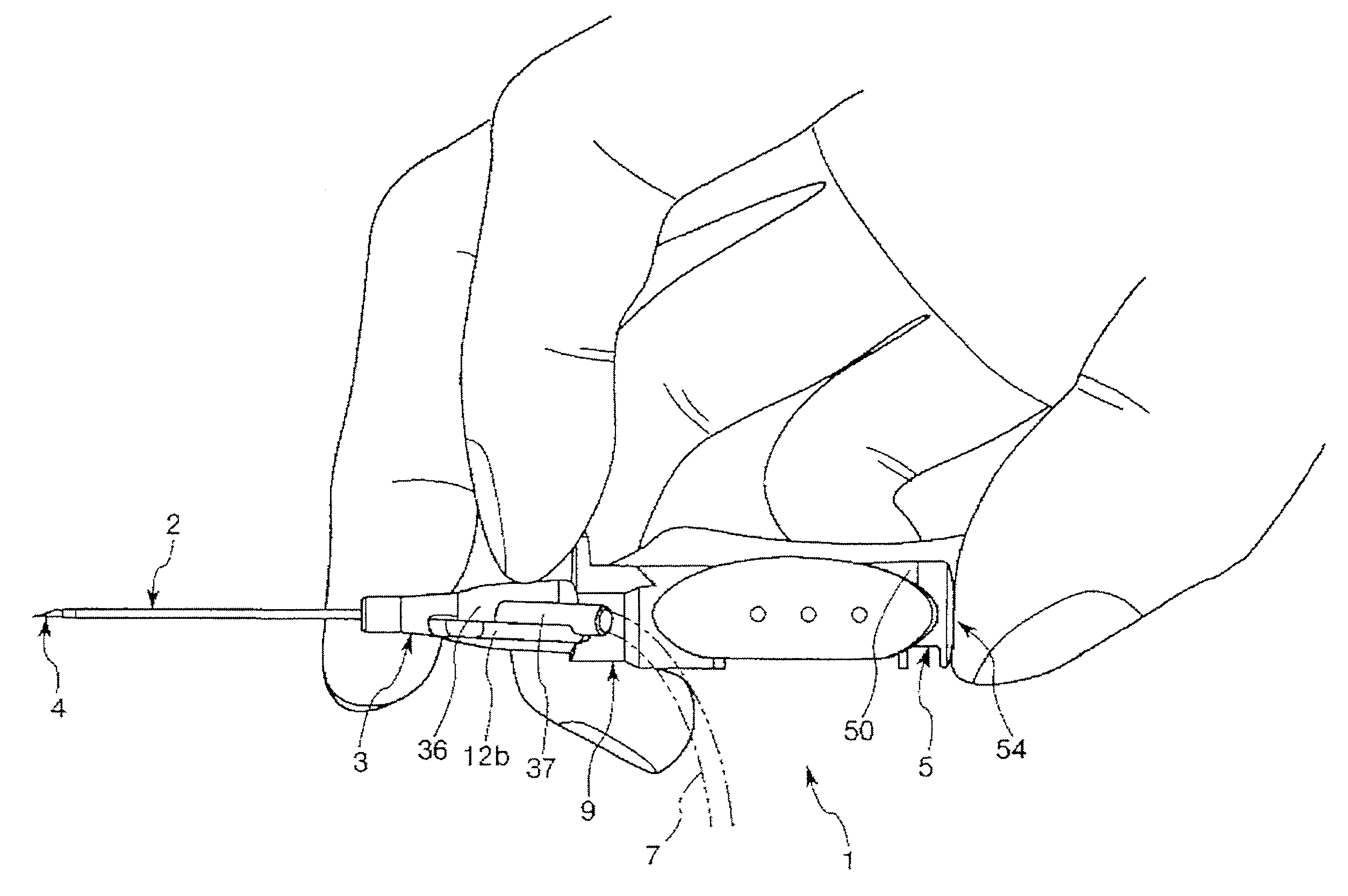
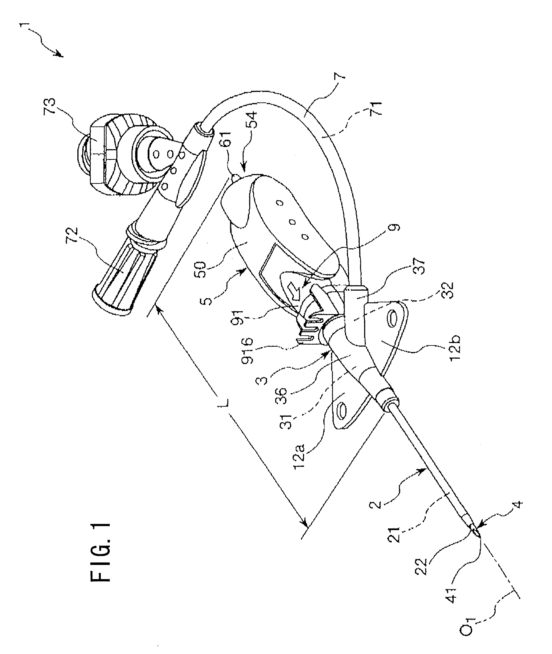
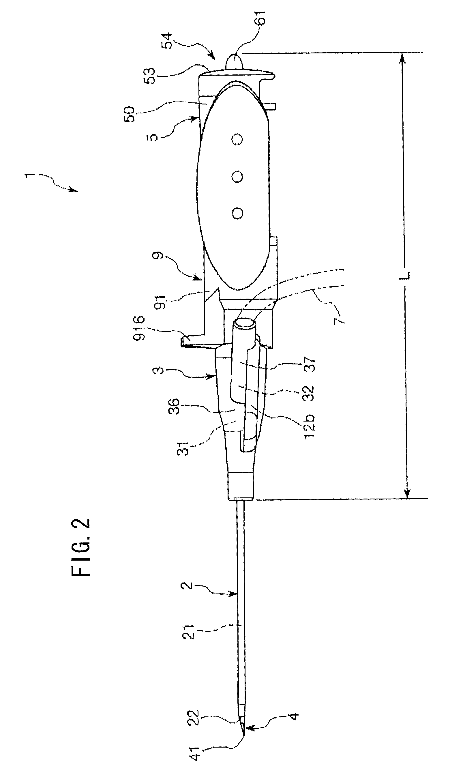
[0056]FIG. 1 is a perspective view showing a first embodiment of the indwelling needle assembly according to an embodiment of the present invention; FIG. 2 is a side view of the indwelling needle assembly shown in FIG. 1; FIG. 3 is a side view showing a condition where the indwelling needle assembly shown in FIG. 1 is held; FIG. 4 is an exploded perspective view of the indwelling needle assembly shown in FIG. 1; FIG. 5 is a sectional view showing an outer needle hub, an inner needle, an inner needle hub, a protector, etc. of the indwelling needle assembly shown in FIG. 1; FIG. 6 is a sectional view taken along line A-A of FIG. 5; FIG. 7 is a sectional view showing the outer needle hub, the inner needle, the inner needle hub, the protector, etc. of the indwelling needle assembly shown in FIG. 1; FIG. 8 is a perspective view showing a coupling member of the protector in the indwelling needle assembly shown in FIG. 1; and FIGS. 9 and 10 each are bottom views showing schematically the o...

second embodiment

[0166]FIGS. 12A, 12B and 12C illustrate a second embodiment of the indwelling needle assembly according to the present invention, wherein FIG. 12A is a side view, FIG. 12B is a sectional view, and FIG. 12C is a rear view. Incidentally, in the following description, the left side in FIGS. 12A and 12B will be referred to as “distal,” and the right side as “proximal (trailing end).”

[0167]Now, the second embodiment will be described below, mainly as to differences thereof from the first embodiment described above, and descriptions of the same items as above will be omitted.

[0168]As shown in FIGS. 12A to 12C, in the indwelling needle assembly 1 according to the second embodiment, an inner needle hub body part 50 is provided at its proximal end face 53 with an annular body 55 which projects toward the proximal side while surrounding the opening of a recess 52. A projected part 61 projects from the inside of the annular body 55 toward the proximal side relative to a proximal end face 551 o...


PUM


Abstract

An indwelling needle assembly, including an inner needle having a sharp needle point at a distal end thereof; an inner needle hub which is fixed to a proximal portion of the inner needle and which has a proximal end face; a hollow outer needle into which the inner needle is inserted; and an outer needle hub fixed to a proximal portion of the outer needle, the inner needle is adhered and fixed to the inner needle hub with an adhesive at a proximal portion thereof, and the inner needle hub is provided with a projected part formed by projecting the adhesive toward a proximal side relative to the proximal end face.

Description

CROSS-REFERENCE TO RELATED APPLICATION[0001]This application is based upon and claims the benefit of priority from Japanese Patent Application No. 2009-196829 filed on Aug. 27, 2009, of which the contents are incorporated herein by reference.BACKGROUND OF THE INVENTION[0002]1. Field of the Invention[0003]The present invention relates to an indwelling needle assembly to be used to puncture a blood vessel and be left indwelling there, in the case of an infusion, for example.[0004]2. Description of the Related Art[0005]At the time of carrying out an infusion on a patient or in other similar situations, an indwelling needle to be connected with an infusion line is made to puncture a patient's blood vessel and is left indwelling for performing the infusion.[0006]Such an indwelling needle assembly, normally, includes a hollow outer needle, an outer needle hub secured to a base end (proximal end) of the outer needle, an inner needle which is inserted into the outer needle and which has a s...

Claims


Application Information

Patent Timeline
Patent Type & Authority Applications(United States)
IPC IPC(8): A61B17/34
CPCA61M5/3275A61M25/0625A61M2005/325A61M2005/3109A61M25/0693
Inventor TANABE, HIDENORIKOBAYASHI, RYOJIMURASHITA, TAKATO
Owner TERUMO KK
Why Eureka
Try Eureka