Paravalvular Leak Closure Devices and Methods

a technology for paravalvular leaks and leaks, which is applied in the field of devices and methods for repairing paravalvular leaks, can solve the problems of paravalvular leakage, high invasiveness of valve surgery, and potential risks for patients, so as to reduce the size of gap, and reduce the size of space

Active Publication Date: 2011-03-03
MEDTRONIC INC
View PDF2 Cites 177 Cited by
  • Summary
  • Abstract
  • Description
  • Claims
  • Application Information

AI Technical Summary

Benefits of technology

In another aspect of the invention, a method of reducing the size of a space between an implanted device and an adjacent tissue within a patient is provided. The method comprises the steps of: inserting an outer sheath into the patient until a distal end of the outer sheath is positioned adjacent to the space; inserting an inner tube into a proximal end of the outer sheath, wherein the inner tube comprises a plurality of needles extending from its distal end; guiding the inner tube through the outer sheath until the needles extend at least partially from the distal end of the outer sheath; positioning the tips of the needles adjacent to the tissue and the implanted device: advancing the needles until they penetrate the tissue and interface with the implanted device: retracting the needles at least partially relative to the sheath to pull the tissue and implanted device closer to each other and reduce the size of the space; applying radio frequency energy to at least one of needles; retracting the needles from the tissue: and removing the inner tube and outer sheath from the patient. It is contemplated, however, that the needles need not interface with the implanted device, but that they instead interface with only the tissue adjacent to the implanted device to shrink the tissue to decrease the size of the gap between the tissue and the implanted device.

Problems solved by technology

This type of valve surgery is highly invasive and exposes the patient to a number of potential risks, such as infection, stroke, renal failure, and adverse effects associated with use of the heart-lung machine, for example.
In either case, the shape of the stent frame in its expanded condition will typically he at least slightly different than the shape of the implantation site, therefore creating the potential for gaps or spaces between the stent frame and the implantation site that allow for paravalvular leakage.
For one example, placing a circular aortic stem in an aortic annulus that has a non-circular shape may result in a gap between the stem and the aortic wall, thereby creating the potential for paravalvular leakage.

Method used


Image

  • Paravalvular Leak Closure Devices and Methods
  • Paravalvular Leak Closure Devices and Methods
  • Paravalvular Leak Closure Devices and Methods

Examples


Embodiment Construction

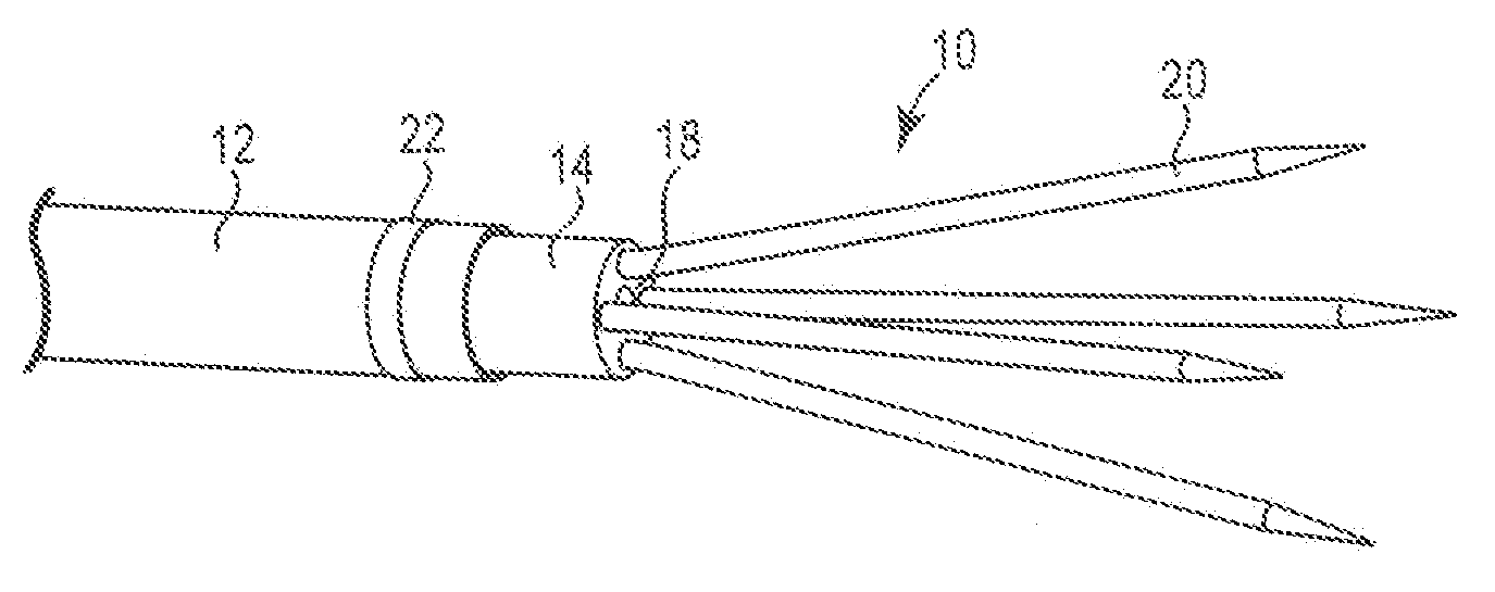
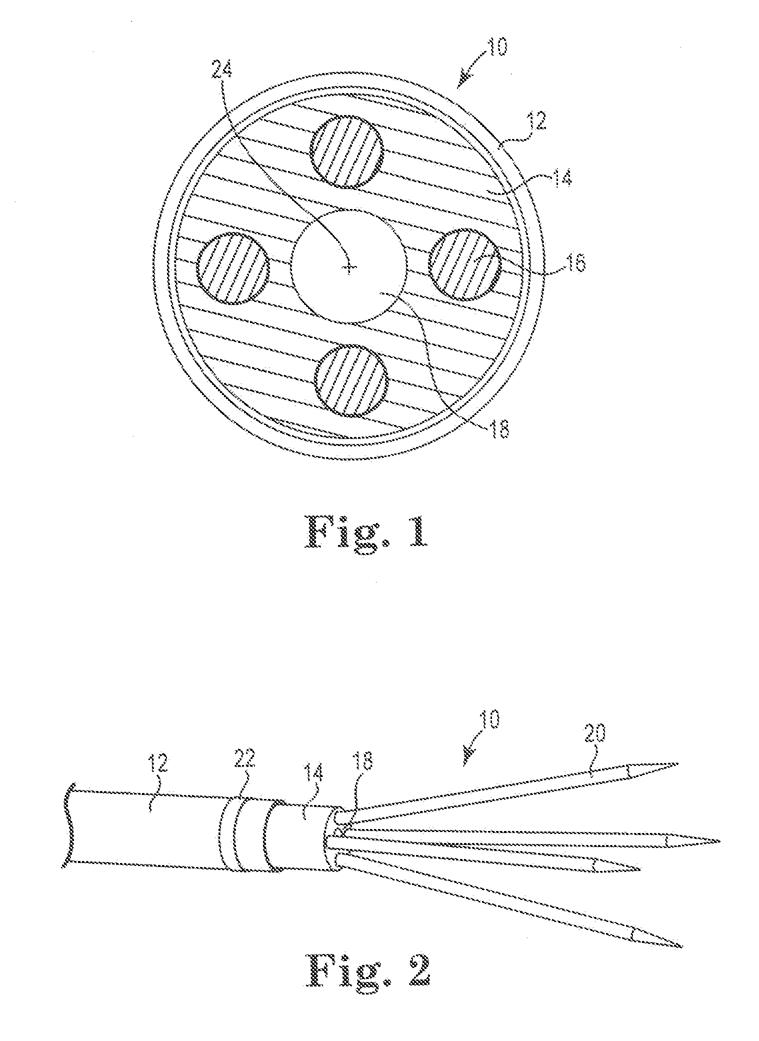
Referring now to the Figures, wherein the components are labeled with like numerals throughout the several Figures, and initially to FIG. 1, one embodiment of a section through the working length of an ablation catheter 10 is illustrated. In general, the working length of the ablation catheter 10 includes an outer tube or sheath 12, which can he made of a flexible material such as nylon, PTFE, PEBAX, or the like, or any combination or blend of such materials. Additionally, sheath 12 can be reinforced with a braid, coil, or other structure to increase its radial stiffness. Outer tube or sheath 12 can at least partially surround an inner tube 14 that is preferably made of a flexible, insulating material, although it can be made of a different type of material. The inner tube 14 includes at least one needle opening or depression 16, each of which is sized to mate with a proximal end of an ablation element: such as a needle or needle electrode. Although four of such needle openings are ...


PUM


Abstract

An ablation catheter including an inner tube having a length, a distal end and a longitudinal axis, a plurality of needles extending from the distal end of the inner tube and biased away from the longitudinal axis, an outer sheath slideably moveable relative to the inner tube to surround at least a portion of the length of the inner tube and its extending needles, and a radio frequency energy source electrically connected to the plurality of needles.

Description

TECHNICAL FIELDThe present invention relates to devices and methods for repairing paravalvular leaks. In particular, the present invention relates to devices and methods for repairing paravalvular leakage using radio frequency (RF) energy.BACKGROUNDDiseased or otherwise deficient heart valves can he repaired or replaced using a variety of different types of heart valve surgeries. One general type of heart valve surgery involves an open-heart surgical procedure that is conducted under general anesthesia, during which the heart is stopped and a heart-lung bypass machine controls blood flow. This type of valve surgery is highly invasive and exposes the patient to a number of potential risks, such as infection, stroke, renal failure, and adverse effects associated with use of the heart-lung machine, for example. Due to the drawbacks of open-heart surgical procedures, there has been an increased interest in minimally invasive and percutaneous replacement of cardiac valves. Such surgical ...

Claims


Application Information

Patent Timeline
Patent Type & Authority Applications(United States)
IPC IPC(8): A61B18/18
CPCA61B18/1477A61B18/1492A61B2018/00011A61F2/82A61B2218/002A61B2218/007A61B2018/143
Inventor ROTHSTEIN, PAUL T.BERGIN, CATHLEEN A.CLAGUE, CYNTHIA T.GREEN, MICHAEL M.HILL, ALEXANDER J.KEOGH, JAMES R.LASKE, TIMOTHY G.
Owner MEDTRONIC INC
Why Eureka
Try Eureka