Autonomous Carrier for Continuously Moving Wing Assembly Line

a technology of autonomous carrier and assembly line, which is applied in the field of manufacturing, can solve the problems of increasing the total amount of time needed the type of assembly may require more time than desired to assemble the wing,

Active Publication Date: 2011-03-03
THE BOEING CO
View PDF11 Cites 100 Cited by
  • Summary
  • Abstract
  • Description
  • Claims
  • Application Information

AI Technical Summary

Problems solved by technology

This type of assembly may require more time than desired to assemble the wing.
As a result, the time needed to move the wing from one station to another station adds to the total amount of time needed to assemble the wing.

Method used


Image

  • Autonomous Carrier for Continuously Moving Wing Assembly Line
  • Autonomous Carrier for Continuously Moving Wing Assembly Line
  • Autonomous Carrier for Continuously Moving Wing Assembly Line

Examples


Embodiment Construction

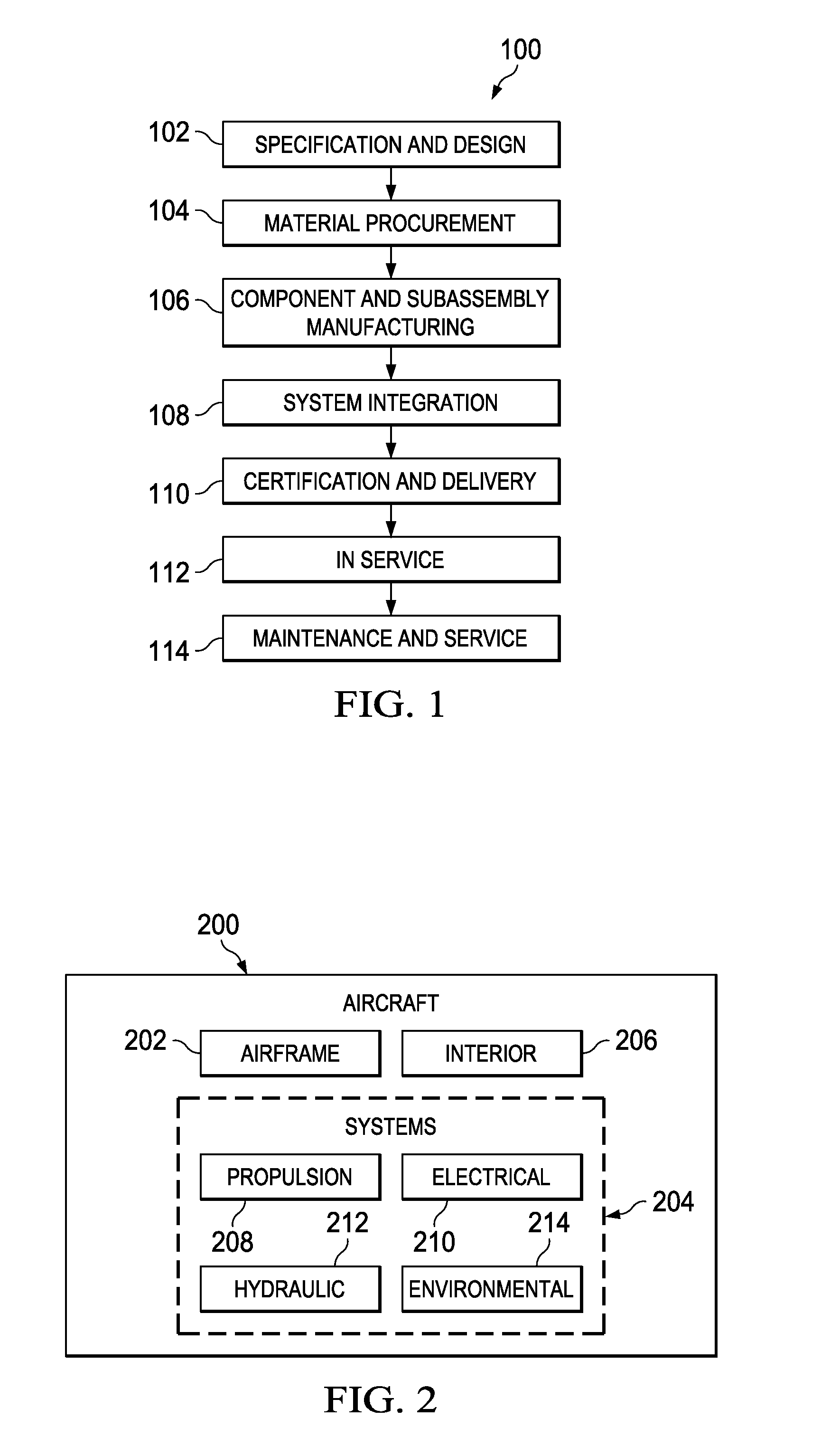
[0030]Referring more particularly to the drawings, embodiments of the disclosure may be described in the context of aircraft manufacturing and service method 100 as shown in FIG. 1 and aircraft 200 as shown in FIG. 2. Turning first to FIG. 1, an illustration of an aircraft manufacturing and service method is depicted in accordance with an advantageous embodiment. During pre-production, aircraft manufacturing and service method 100 may include specification and design 102 of aircraft 200 in FIG. 2 and material procurement 104.

[0031]During production, component and subassembly manufacturing 106 and system integration 108 of aircraft 200 in FIG. 2 takes place. Thereafter, aircraft 200 in FIG. 2 may go through certification and delivery 110 in order to be placed in service 112. While in service 112 by a customer, aircraft 200 in FIG. 2 is scheduled for routine maintenance and service 114, which may include modification, reconfiguration, refurbishment, and other maintenance or service.

[0...


PUM

PropertyMeasurementUnit
movementaaaaaaaaaa
distanceaaaaaaaaaa
structureaaaaaaaaaa

Abstract

A method and apparatus for moving a structure. The structure is supported on a carrier. The carrier comprises a platform having a first side and a second side, a movement system associated with the first side and configured to move the platform on a surface, a support system associated with the second side of the platform and configured to support the structure on the platform, and a leveling system configured to substantially maintain the structure in a desired orientation during movement of the platform on the surface. The carrier is moved with the structure over the surface. At least one of the movement system and the support system is adjusted to substantially maintain the structure in the desired orientation.

Description

BACKGROUND INFORMATION[0001]1. Field[0002]The present disclosure relates generally to manufacturing and, in particular, to a method and apparatus for manufacturing aircraft. Still more particularly, the present disclosure relates to a method and apparatus for moving aircraft structures during a manufacturing process.[0003]2. Background[0004]In manufacturing aircraft, portions of an aircraft are assembled and then put together to form the aircraft. For example, the fuselage of an aircraft may be formed by assembling a structure, such as a frame. Thereafter, skin panels may be attached to the frame to form the fuselage. As another example, with composite materials, the fuselage may be created in cylindrical sections. These different cylindrical sections may be put together to form the fuselage of an aircraft.[0005]In yet another example, wings, horizontal stabilizers, and vertical stabilizers may be assembled from smaller pieces or components. For example, with a wing, ribs, spars, an...

Claims


Application Information

Patent Timeline
Patent Type & Authority Applications(United States)
IPC IPC(8): G05D3/12G05B13/02
CPCB23P2700/01B25B11/02Y10T29/53961Y10T29/53978B64F5/0009B64F5/10B23P19/00B64F5/50
Inventor MUNK, CLAYTON L.
Owner THE BOEING CO
Why Eureka
Try Eureka