Dual Path Kiln Improvement

a dual-path, kiln technology, applied in the direction of rope railways, drying machines with progressive movements, lighting and heating apparatus, etc., can solve the problems of adding to the cost of finished lumber, and achieve the effects of increasing the speed of load transport, increasing stability, and increasing speed

Active Publication Date: 2011-03-10
TINSLEY DOUGLAS M +3
View PDF99 Cites 21 Cited by
  • Summary
  • Abstract
  • Description
  • Claims
  • Application Information

AI Technical Summary

Benefits of technology

[0003]In the present invention, an improvement in the pusher mechanism, or load mover, for each load moved along the separate paths is provided where greater stability is assured for the lumber positioned on the carriages that are pushed on rails by separate pushing devices in which one is provided for each path. In particular, each pusher device is provided with a faceplate that engages the end of the load to be moved into the kiln with the faceplate extending over a significant area of the end of the load. Further, to allow increased speeds, the faceplate has extending arms to engage the sides of...

Problems solved by technology

As will be evident to those skilled in this technology, this was a labor-intensiv...

Method used


Image

  • Dual Path Kiln Improvement
  • Dual Path Kiln Improvement
  • Dual Path Kiln Improvement

Examples


Embodiment Construction

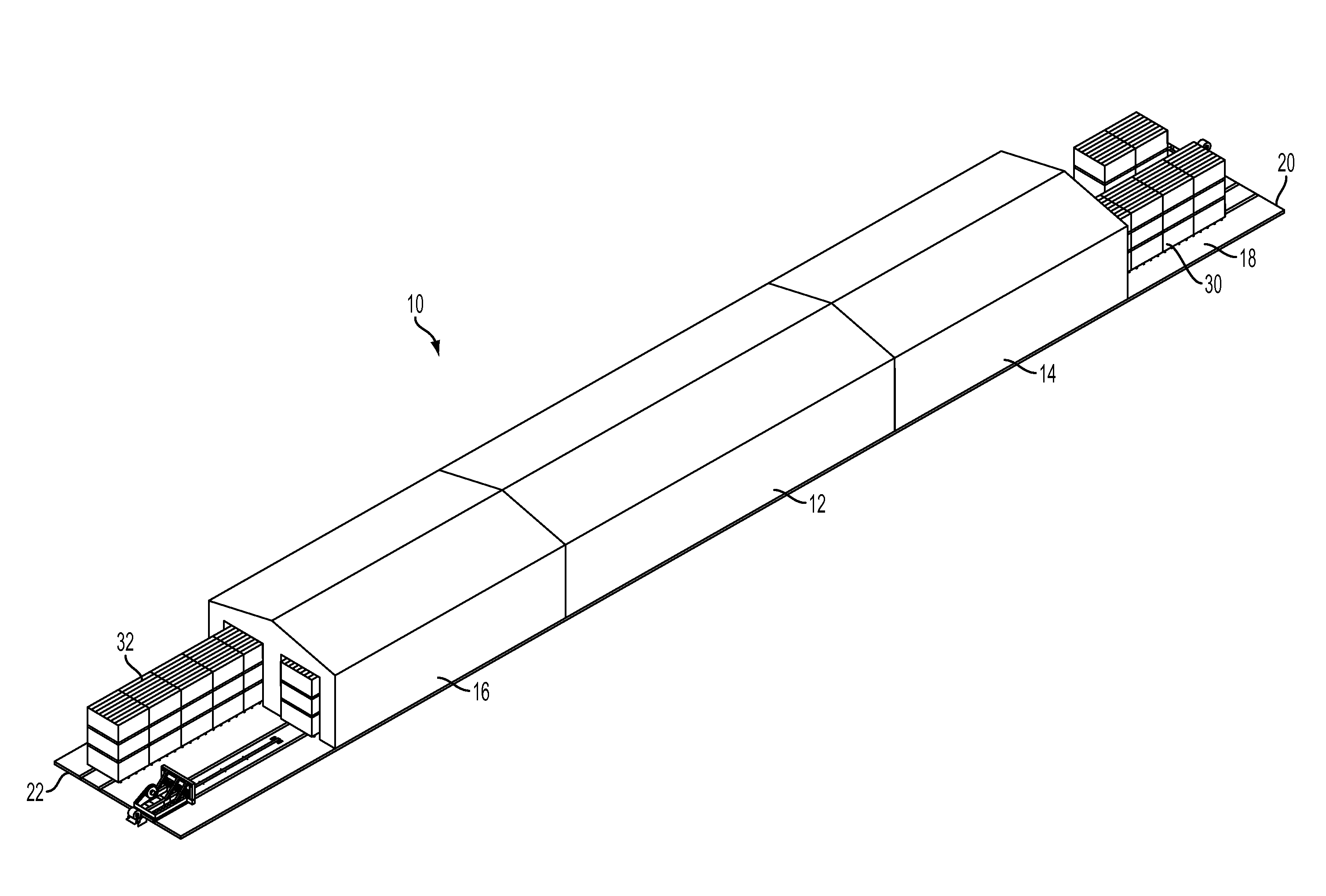
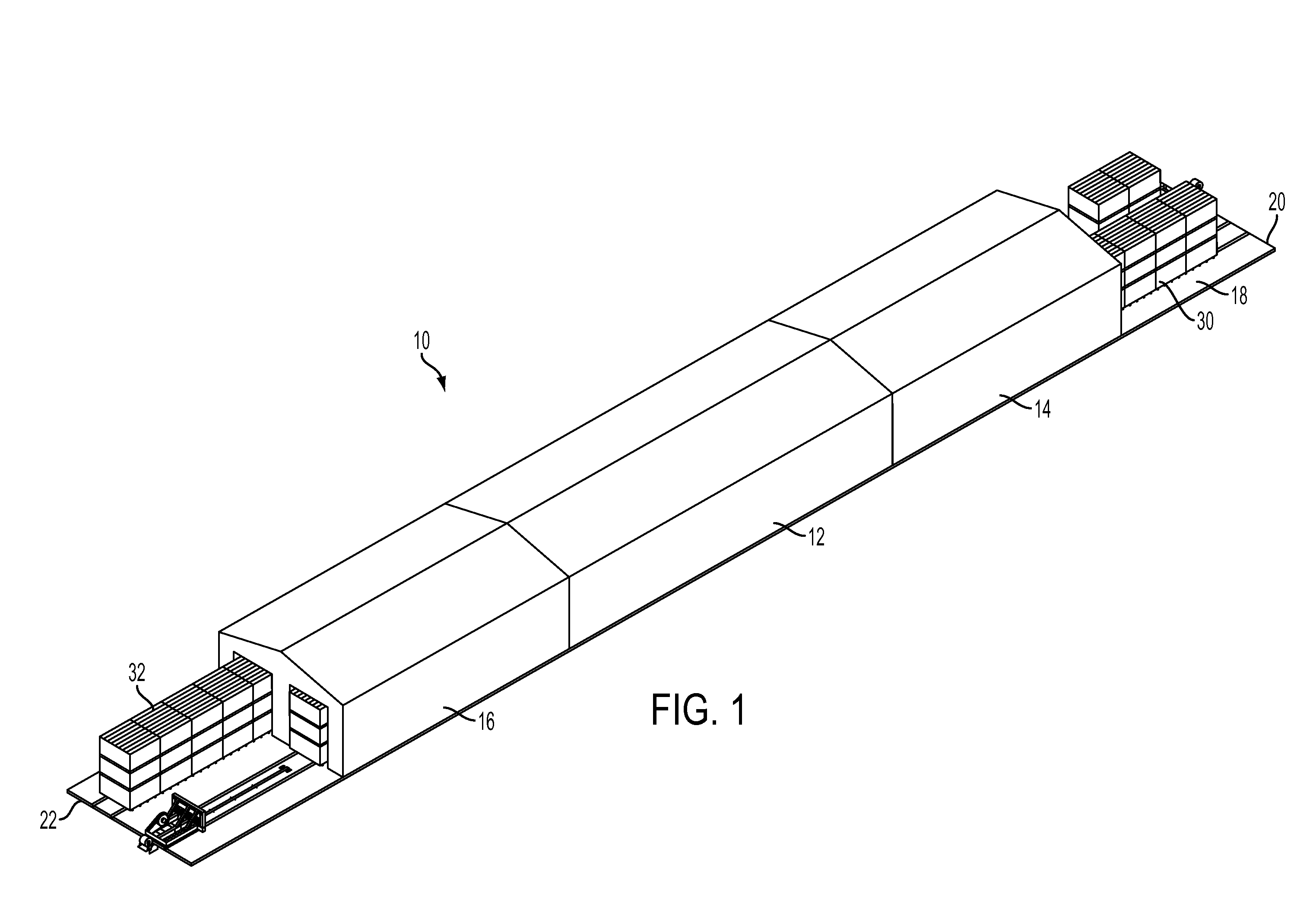
[0011]Referring to the non-limiting Figures wherein like numerals designate corresponding parts throughout the various views, there is shown, in FIG. 1, a continuous kiln which typically will include a main heating chamber 12 and opposite end chambers 14 and 16 where heat transfer between the paths will take place aided typically by fans positioned to transfer heat between the passing loads of lumber as they are moved past one another. The base of the kiln 10 may be extended from an entry 22 located at opposite ends of the structure through the chambers 12, 14 and 16 and may include two pairs of parallel rails for each path. As shown in broken lines in FIG. 3, carriages 24 having wheels for engaging the rails 26 are provided and on which the loads of lumber 30, 32 are loaded at the opposite ends 20 and 22 of the base 18. In a typical arrangement, one end of a load of boards will be stacked on the forward carriage 24 while the rear end of the load of boards will rest on the trailing ...


PUM


Abstract

A dual path kiln is provided that includes a kiln having one or more chambers and at least two lumber charge paths adapted to convey lumber through the kiln in opposite directions by means of a track having two rails in which a pusher device pushes the lumber through the kiln and comprises a variable output electric motor to effect a high degree of accurate control of the movement speed of the pusher device and the lumber it's pushing and wherein the pusher device includes a faceplate having two side walls extending from said faceplate to engage the side of the lumber in order to greatly enhance stability of the lumber while it is being transported and minimize the risk of spillage.

Description

FIELD OF THE INVENTION [0001]The present invention relates to the field of lumber handling and more specifically, the present invention is directed to drying equipment for preparing raw lumber for sale. As is well known, fresh cut lumber includes a large quantity of moisture and it has been the practice to subject such lumber to heat treatment to drive off the moisture so that the lumber, as sold, will be less subject to warping or bending during storage or after installation in a structure.BACKGROUND [0002]As described in co-pending application Ser. No. 11 / 525,929 filed Sep. 25, 2006 and incorporated by reference herein, in this field, lumber drying was typically performed in a batch process where a quantity of raw moisture laden lumber is piled in one or more stacks and the stacks were moved into a kiln with an insulated chamber through which heated air was moved to effect removal of moisture from the lumber. As will be evident to those skilled in this technology, this was a labor...

Claims


Application Information

Patent Timeline
IPC IPC(8): F26B25/06F26B25/08
CPCF26B2210/16F26B15/16
Inventor TINSLEY, DOUGLAS M.FREEMAN, TERRY R.SMOKE, WILLIAM S.POLLARD, LEVI A.
Owner TINSLEY DOUGLAS M
Why Eureka
Try Eureka