
Back-carried work apparatus

a work apparatus and backcarrying technology, applied in the field of backcarrying work apparatuses, can solve the problems of reducing the effective working time, comparatively large residual amount of fuel cannot be drawn, and comparatively large amount of fuel cannot be extracted, and achieve the effect of simple configuration

Inactive Publication Date: 2011-03-10
ANDREAS STIHL AG & CO KG
View PDF32 Cites 11 Cited by
  • Summary
  • Abstract
  • Description
  • Claims
  • Application Information

AI Technical Summary

Benefits of technology

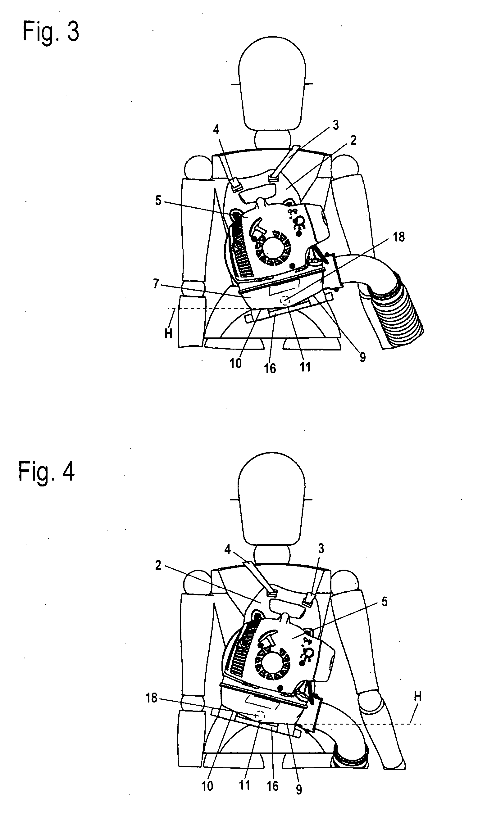
The invention is a back-carried work apparatus with a fuel tank that can be easily filled and has a simple configuration. The tank has a tank base with a narrowed area called the lowest area, which allows for easy fuel extraction even when the tank is only partially full. The tank base is inclined relative to the horizontal level when the shoulder straps are on the operator, and the fuel tank is designed in a funnel-like manner to maximize fuel extraction. The work apparatus can be carried with either one or both shoulder straps, and the tank base is designed to have a high fill level with minimal residual fuel. The invention is especially useful for elongated tanks.

Problems solved by technology

Because the base of the tank is typically essentially even, a comparatively large residual amount of fuel cannot be drawn even on work apparatuses which are carried horizontally.
When the suction head is in a disadvantageous position a comparatively large amount of fuel cannot be extracted.
As a result, frequent filling of the fuel tank is necessary, which considerably reduces the effective working time.

Method used


Image

  • Back-carried work apparatus
  • Back-carried work apparatus
  • Back-carried work apparatus

Examples


Embodiment Construction

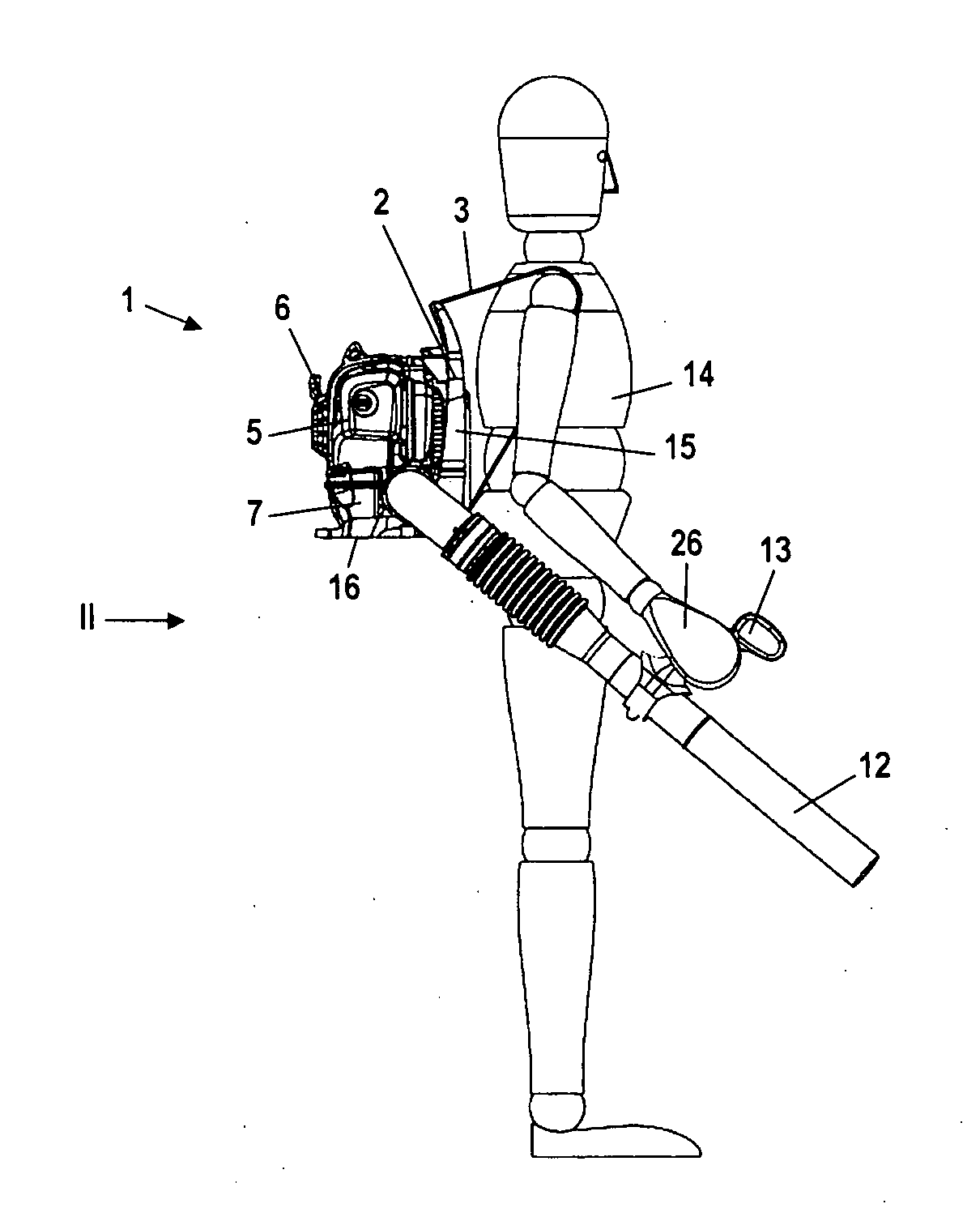
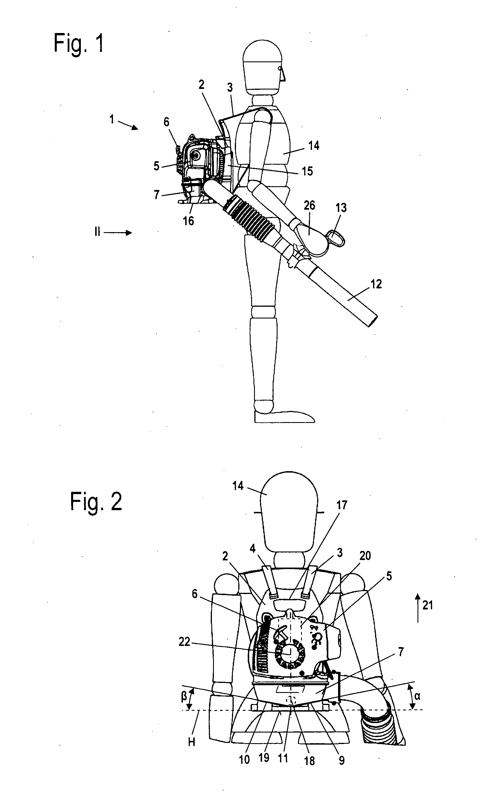
FIG. 1 shows as an example embodiment a blower 1 as a back-carried work apparatus. The blower 1 has a back carrier 2 which is carried on the back of an operator 14 with the shoulder straps 3 and 4 (FIG. 2). The back carrier 2 includes a back carrier plate 15, which advantageously rests on the back of the operator 14 and can be braced against the back via pads, as well as a base plate 16. A housing 5 of the blower 1 is held on the back carrier 2. The blower 1 has a fuel tank 7 which is arranged underneath the housing 5. The fuel tank 7 can, however, also be arranged in the housing 5 or be integrated into the housing 5. As FIG. 1 shows, a start handle 6 of a starting arrangement projects out of the housing 5. The blower 1 has a blower tube 12 on which an operating handle 13 is arranged. The operator 14 can hold and guide the blower tube 12 via the operating handle 13 with one hand 26, here with the right hand 26.

The start handle 6 serves to start a drive motor 20 arranged in the housi...


PUM


Abstract

A back-carried work apparatus has a back carrier (2), which has two shoulder straps (3, 4) to carry the back carrier (2) on a back and carries a drive motor (20). The drive motor (20) is configured as a combustion engine. A fuel tank (7) for the drive motor (20) is arranged on the back carrier (2). In order to make fuel extraction possible up to the least possible amount of residual, the tank base (8, 28) of the fuel tank (7) has a lowest region which extends over less than 20% of the width (d) of the tank base (8, 28) when the shoulder straps (3, 4) are arranged on the shoulders of the operator.

Description

CROSS REFERENCE TO RELATED APPLICATIONThis application claims priority of German patent application no. 10 2009 040 494.5, filed Sep. 8, 2009, the entire content of which is incorporated herein by reference.FIELD OF THE INVENTIONThe invention relates to a back-carried work apparatus.BACKGROUND OF THE INVENTIONBack-carried work apparatuses typically have an elongated tank extending over the entire width of the work apparatus. A suction head is typically provided to draw fuel. For the suction head to be able to deliver fuel, a minimum fill level of the fuel is needed in the area of the suction head. Because the base of the tank is typically essentially even, a comparatively large residual amount of fuel cannot be drawn even on work apparatuses which are carried horizontally. The amount of fuel which cannot be extracted can become noticeably larger when the back carrier is not carried horizontally, for example, when the operator only has one shoulder strap on one shoulder, so that the ...

Claims


Application Information

Patent Timeline
Patent Type & Authority Applications(United States)
IPC IPC(8): F02B63/02
CPCA01G1/12A45F2003/146A45F3/14A01G20/47A01G20/30
Inventor SCHLIEMANN, HARALD
Owner ANDREAS STIHL AG & CO KG
Learn More