Structure of crankcase

Inactive Publication Date: 2011-03-10
MITSUBISHI HEAVY IND LTD
View PDF7 Cites 0 Cited by
  • Summary
  • Abstract
  • Description
  • Claims
  • Application Information

AI Technical Summary

Benefits of technology

[0015]In view of the above issues, an object of the present invention is to provide a structure of a crankcase which is capable of coping with increased combustion pressure inside a cylinder of an engine having a plurality of cylinders (in-line cylinders) with a means for suppressing the deformation near a middle section (section Z) between fastening bolts in a direction parallel to a center-connecting line (horizontal line) connecting centers of the pair of the adjacent cylinders.
[0021]According to the present invention, in the structure of the crankcase, the deformation of the cylinder top plate is substantially high at the middle section between fastening bolts in a direction parallel to a center-connecting line (horizontal line) connecting centers of the pair of the adjacent cylinders as there are only few bosses around the middle section. In the present invention, the reinforcing rib is formed on the outer wall of the cylinder at the middle section in the direction connecting centers of the adjacent cylinders and the reinforcing rib extends downward continuously from the bottom surface of the cylinder top plate in a direction parallel to the center line of the cylinder so as to improve the rigidity at the middle section and further prevents the droop of the top plate toward inside of the cylinder, thereby preventing the deformation of the cylinder top plate.
[0022]Therefore, the crankcase of the engine, which is capable of coping with increased combustion pressure inside the cylinder due to a high supercharging and a high output of an engine can be obtained by simply adding the reinforcing rib of a simple and inexpensive structure requiring only few extra processes, which can suppress the deformation at the middle section between the fastening bolts in the center-connecting line.
[0023]Further, the reinforcing rib is provided at each of the middle sections between the adjacent fastening bolts in the direction connecting centers of the adjacent cylinders where the rigidity of the outer wall is the smallest so as to improve the rigidity and average out the deformation of the cylinder top plate.
[0024]Furthermore, the reinforcing rib is provided at each of the middle sections and the reinforcing rib has a semicircular cross-sectional shape in the same manner as bosses for the fastening bolts so as to improve the rigidity and simplify the molding thereof.
[0025]Moreover, the reinforcing rib connects to the vertical part of the crankcase at the connection section thereof arranged lower than a supporting boss of the crankcase for supporting the cylinder liner so as to suppress the falling-down deformation of the supporting boss toward inside of the cylinder when the cylinder liner is supported by the supporting boss.

Problems solved by technology

However, at the middle sections Z between the fastening bolts 3 on the horizontal line 20 (the middle sections Z are located on the vertical line of the cylinder center), the number of the bosses is small and thus the deformation is more evident and it is difficult to reinforce the area.

Method used


Image

  • Structure of crankcase
  • Structure of crankcase
  • Structure of crankcase

Examples


Embodiment Construction

[0030]A preferred embodiment of the present invention will now be described in detail with reference to the accompanying drawings. It is intended, however, that unless particularly specified, dimensions, materials, shape, its relative positions and the like shall be interpreted as illustrative only and not limitative of the scope of the present.

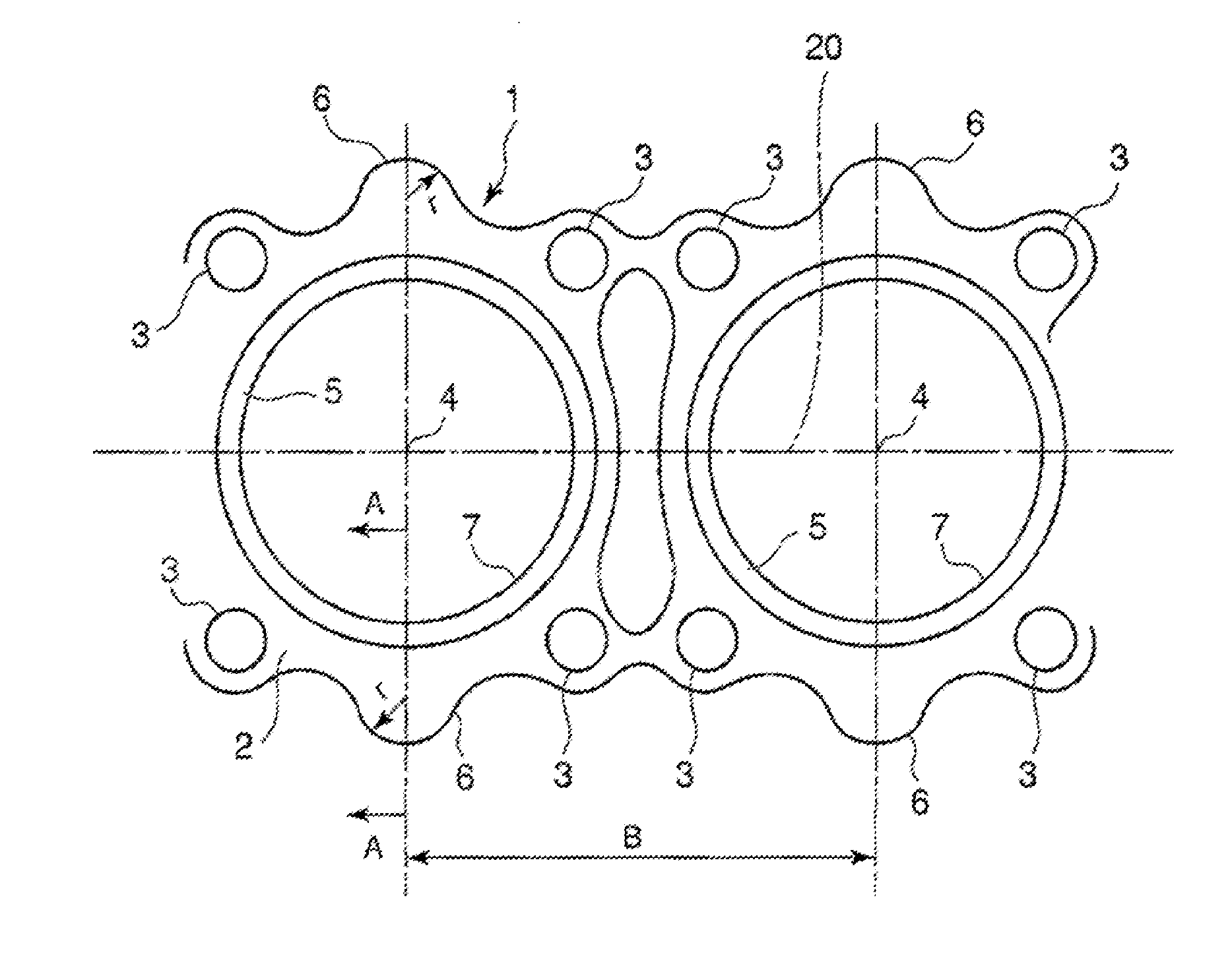
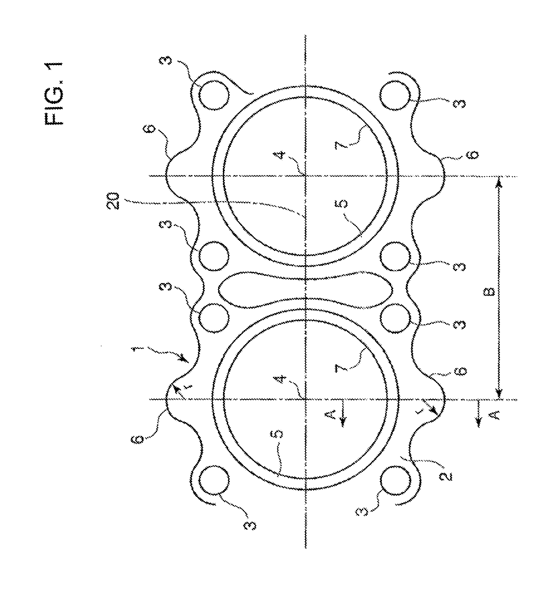
[0031]FIG. 1 is a plain view of main parts of a crankcase for a diesels engine relating to a preferred embodiment of the present invention.

[0032]In FIG. 1, a crankcase 1 comprises two cylinders in line installed upright adjacent to each other. Further, a plurality of bolts for fastening each of the cylinders 7 to a cylinder head are provided on a cylinder wall arranged around each of the cylinders. Throughout the drawings, the fastening bolts are shown as fastening bolt holes 3. In FIG. 1, head bolt reinforcing members 3a are provided around the cylinder hole and each of the reinforcing members protrudes around the cylinder hole by 45 degree ...


PUM


Abstract

An object of the present invention is to propose a structure of a crankcase capable of coping with increased combustion pressure inside a cylinder of an engine by a simple and inexpensive means for suppressing the deformation at a middle section between adjacent fastening bolts in a direction connecting the centers of adjacent cylinders. The structure of the crankcase which has a plurality of cylinders and a plurality of bolts arranged on both sides of each of the cylinders for fastening the cylinders to a cylinder head, the structure of the crankcase comprises a reinforcing rib 6 formed on an outer wall of the cylinder at a middle section between the adjacent fastening bolts 3 in a direction 20 connecting centers of the adjacent cylinders, the reinforcing rib extending downward continuously from the cylinder top plate in a direction parallel to a center line 4a of the cylinder.

Description

BACKGROUND OF THE INVENTION[0001]1. Field of the Invention[0002]The present invention relates to a structure of a crankcase which is applicable to a diesel engine and has a plurality of cylinders having plural bolts on both sides of each cylinder for fixing to a cylinder head.[0003]2. Description of the Related Art[0004]Many means have been tried to improve the strength of crankcase components of a diesel engine of recent years with higher supercharging and higher output.[0005]FIG. 4 is a plain view of main parts of a cylinder block from above as an example of a conventional crankcase for a diesel engine having two cylinders.[0006]In FIG. 4, a crankcase 1 comprises two cylinders in line installed upright adjacent to each other. Further, a plurality of bolts for fastening each of the cylinders 7 to the cylinder head are provided on a cylinder wall arranged around each of the cylinders. Throughout the drawings, the fastening bolts are shown as fastening bolt holes 3. In FIG. 4, head b...

Claims


Application Information

Patent Timeline
IPC IPC(8): F02F7/00
CPCF02F7/0007
Inventor TSUKAMOTO, TARO
Owner MITSUBISHI HEAVY IND LTD
Why Eureka
Try Eureka