Method for realizing variable compression ratio and variable air-fuel ratio of internal combustion engine

Inactive Publication Date: 2017-05-25
YANG ZENGLI
View PDF6 Cites 0 Cited by
  • Summary
  • Abstract
  • Description
  • Claims
  • Application Information

AI Technical Summary

Benefits of technology

The present invention provides a method to achieve a variable compression ratio and variable air-fuel ratio in an internal combustion engine to reduce combustion temperature, increase combustion pressure, and improve utilization of combustion heat. This results in a reduction of exhaust temperature from 1,200°C to 180°C-300°C and greatly improved thermal efficiency of the engine.

Problems solved by technology

However, the higher the combustion temperature is, the more heat is taken away by the exhaust gas.
Therefore, the thermal efficiency of the conventional internal combustion engine is only about 30%, which means that 70% of the combustion heat is directly discharged into the atmosphere without participating in working.
The ultra-expansion working can increase the expansion volume to reduce the exhaust pressure, but the exhaust temperature cannot be further lowered.
The root cause lies in the inherent flaw of the high combustion temperature of the conventional internal combustion engine.

Method used


Image

  • Method for realizing variable compression ratio and variable air-fuel ratio of internal combustion engine
  • Method for realizing variable compression ratio and variable air-fuel ratio of internal combustion engine
  • Method for realizing variable compression ratio and variable air-fuel ratio of internal combustion engine

Examples


first embodiment

[0059]This embodiment is a four-stroke spark ignition internal combustion engine;

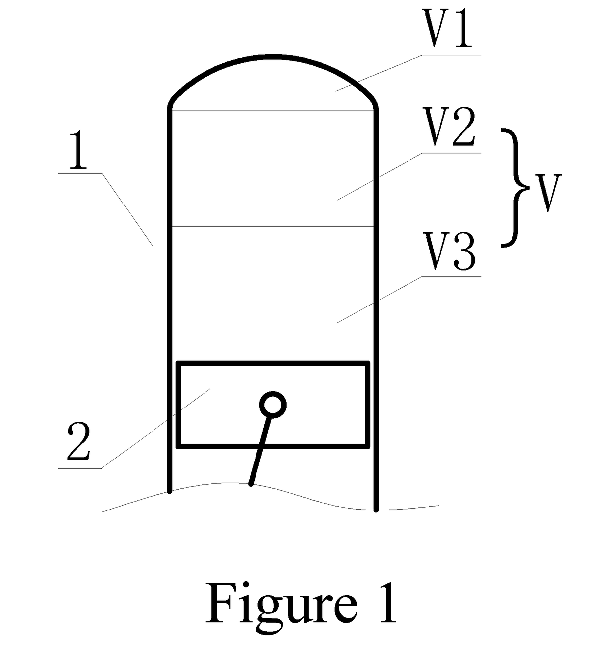
[0060]the cylinder working volume is 400 ml, and the combustion chamber volume V1 is designed as 15 ml;

[0061]the air intake volume V2 of the low power operating condition is 150 ml;

[0062]the compression ratio of the low power operating condition is 10:1;

[0063]the air-fuel ratio of the low power operating condition is 15:1;

[0064]the air intake volume V3 of the high power operating condition is 250 ml;

[0065]the range of variable compression ratio of the high power operating condition is 10:1-26.7:1; and

[0066]the range of variable air-fuel ratio of the high power operating condition is 15:1-32:1;

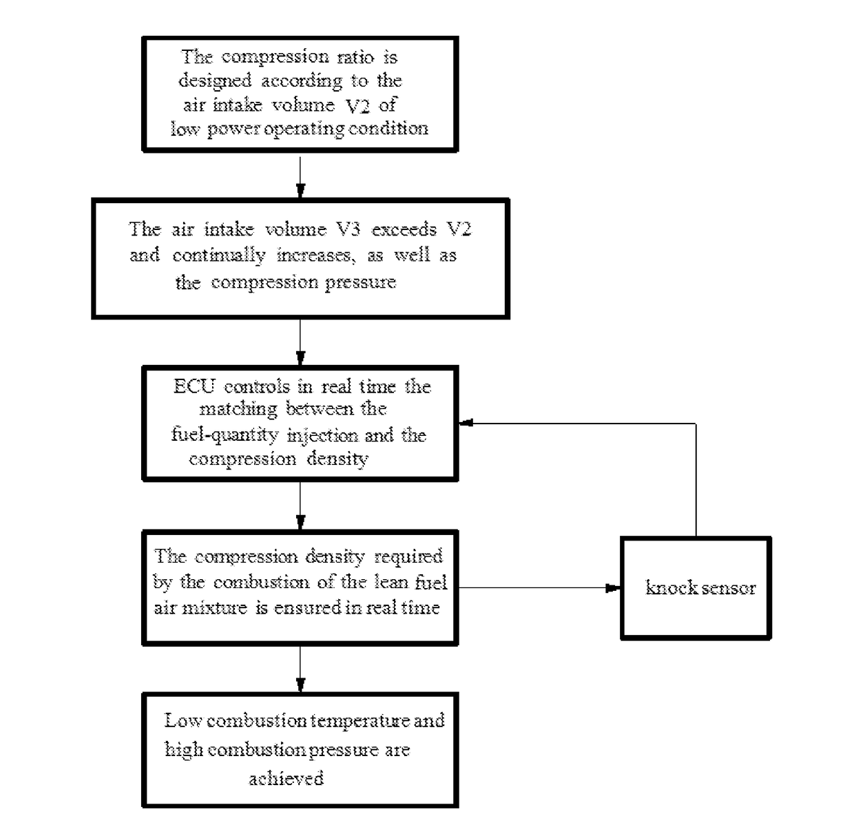
[0067]In this embodiment, the compression ratio is designed according to the air intake volume V2 of the low power operating condition, and as long as the intake air volume reaches V2, it is considered to reach the designed compression ratio. The air intake volume V2 of the low power operating condition is 150 ml, ...

second embodiment

[0072]This embodiment is a four-stroke spark ignition internal combustion engine;

[0073]the cylinder working volume is 600 ml, and the combustion chamber volume V1 is designed as 15 ml;

[0074]the air intake volume V2 of the low power operating condition is 210 ml;

[0075]the compression ratio of the low power operating condition is 14:1;

[0076]the air-fuel ratio of the low power operating condition is 18:1;

[0077]the air intake volume V3 of the high power operating condition is 360 ml;

[0078]the range of variable compression ratio of the high power operating condition is 14:1-40:1; and

[0079]the range of variable air-fuel ratio of the high power operating condition is 18:1-50:1;

[0080]In this embodiment, the compression ratio is designed according to the air intake volume V2 of the low power operating condition, and as long as the intake air volume reaches V2, it is considered to reach the designed compression ratio. The air intake volume V2 of the low power operating condition is 210 ml, th...

third embodiment

[0085]This embodiment is a four-stroke compression ignition internal combustion engine, in which a throttle is needed to be additionally installed;

[0086]the cylinder working volume is 1,200 ml, and the combustion chamber volume V1 is designed as 25 ml;

[0087]the air intake volume V2 of the low power operating condition is 500 ml;

[0088]the compression ratio of the low power operating condition is 20:1;

[0089]the air-fuel ratio of the low power operating condition is 16:1;

[0090]the air intake volume V3 of the high power operating condition is 700 ml;

[0091]the range of variable compression ratio of the high power operating condition is 20:1-48:1; and

[0092]the range of variable air-fuel ratio of the high power operating condition is 16:1-60:1;

[0093]In this embodiment, the compression ratio is designed according to the air intake volume V2 of the low power operating condition, and as long as the intake air volume reaches V2, it is considered to reach the designed compression ratio. The air...


PUM


Abstract

A method for realizing a variable compression ratio and a variable air-fuel ratio of an internal combustion engine includes the following steps of: dividing an air intake volume in a cylinder into a first air intake volume and a second air intake volume, designing a compression ratio according to the first air intake volume and opening a throttle to enable the air intake volume to reach the first air intake volume; increasing the opening of the throttle to increase an air inflow to enable the second air intake volume to start intake, and correcting, by an electronic control unit, a duration of ignition in real time according to a detonation signal fed back by a knock sensor, and controlling a fuel-injection quantity in real time to ensure the compression density required by combustion of a lean fuel air mixture.

Description

CROSS REFERENCE OF RELATED APPLICATION[0001]This is a U.S. National Stage under 35 U.S.C 371 of the International Application PCT / CN2014 / 000624, filed Jun. 27, 2014.BACKGROUND OF THE PRESENT INVENTION[0002]Field of Invention[0003]The present invention relates to an internal combustion engine, and in particular, relates to a method for realizing variable compression ratio and variable air-fuel ratio of an internal combustion engine.[0004]Description of Related Arts[0005]In recent years, with the raised requirements of the economy for the internal combustion engine and stricter regulations on internal combustion engine emissions, to improve the internal combustion engine fuel economy and emissions performance has become the endeavor direction of designing and manufacturing.[0006]Conventional internal combustion engines have always sought to increase the combustion temperature, by which means the combustion pressure can be increased. However, the higher the combustion temperature is, t...

Claims


Application Information

Patent Timeline
IPC IPC(8): F02D41/14F02D15/00F02D41/18
CPCF02D41/1498F02D15/00F02D41/182F02D9/02F02D35/027F02D41/0002F02B2075/025F02D2700/035Y02T10/40F02D15/02F02D15/04
Inventor YANG, ZENGLI
Owner YANG ZENGLI
Why Eureka
Try Eureka