Working machine

a technology of working machine and working plate, which is applied in the direction of folding cycle, washstand, carriage/perambulator with multiple axes, etc., can solve the problems of undesirable movement (positional shift), and increased weight and cost of working pla

Active Publication Date: 2011-03-10
HONDA MOTOR CO LTD
View PDF14 Cites 4 Cited by
  • Summary
  • Abstract
  • Description
  • Claims
  • Application Information

AI Technical Summary

Benefits of technology

[0006]In view of the foregoing prior art problems, it is an object of the present invention to provide an improved working machine which can reliably protect to-be-protected members, such as an operation start / stop switch, without increasing the number of necessary component parts.
[0008]In the present invention, the handle in the stored position projects outwardly beyond the top section and the wall section (e.g., front wall section); namely, the top section and the wall section of the machine body are located inwardly of the handle. Thus, the to-be-protected members provided on the top section and the wall section can be protected with the handle. Namely, the handle can also be used as a member for protecting the to-be-protected members, and thus, the present invention can effectively protect the to-be-protected members, provided on the top section and the wall section, without providing dedicated guard members, thereby avoiding an increase in the number of necessary component parts.
[0009]Preferably, the handle in the stored position is disposed along outer peripheral portions of opposed side wall sections (e.g., left and right side wall sections) of the machine body which are located adjoining the predetermined wall section, and the handle in the stored position projects outwardly beyond the opposed side wall sections. Thus, the opposed side wall sections of the machine body are located inwardly of the handle. Therefore, any desired to-be-protected members can be provided on the opposed side wall sections and can be effectively protected with the handle. As a result, the present invention can achieve an enhanced design freedom. Because the handle can also be used as a member for protecting the to-be-protected members provided on the opposed side wall sections, and thus, the present invention can avoid an increase in the number of necessary component parts.
[0012]Thus, there can be secured a greater length between the support shaft and a handle grip than in the conventionally-known working machines where the handle is formed in a straight shape. Thus, when the handle is in the deployed position, the handle grip can be positioned at an easy-to-grip position sufficiently remote from the machine body. Therefore, usability or operability of the handle and hence the working machine can be enhanced. Further, the handle, formed in an L shape as viewed in side elevation as noted above, is retained (locked) in the deployed position during towing of the working machine.
[0013]Thus, if the working machine has toppled down as a result of the human operator accidentally taking his or her hand off the handle grip during the towing of the working machine, the corner portion, projecting generally in the machine-towing direction beyond the support shaft, can abut against a road surface (ground surface). Thus, it is possible to prevent the support shaft from undesirably abutting against the road surface to be damaged.

Problems solved by technology

However, when the working machine is carried in the vehicle, it may undesirably move (positionally shift) from an initial vehicle-mounted position due to vibration and acceleration / deceleration of the vehicle during travel of the vehicle.
By such positional shift of the working machine, the to-be-protected members, such as the electric outlet and an operation start / stop switch, that need to be protected might be undesirably interfered with and even damaged by other luggage loaded in the vehicle and projecting members of the vehicle.
In such a case, however, the number of necessary component parts would increase, which would lead to an increased weight and cost of the working machine.

Method used


Image

  • Working machine
  • Working machine
  • Working machine

Examples


Embodiment Construction

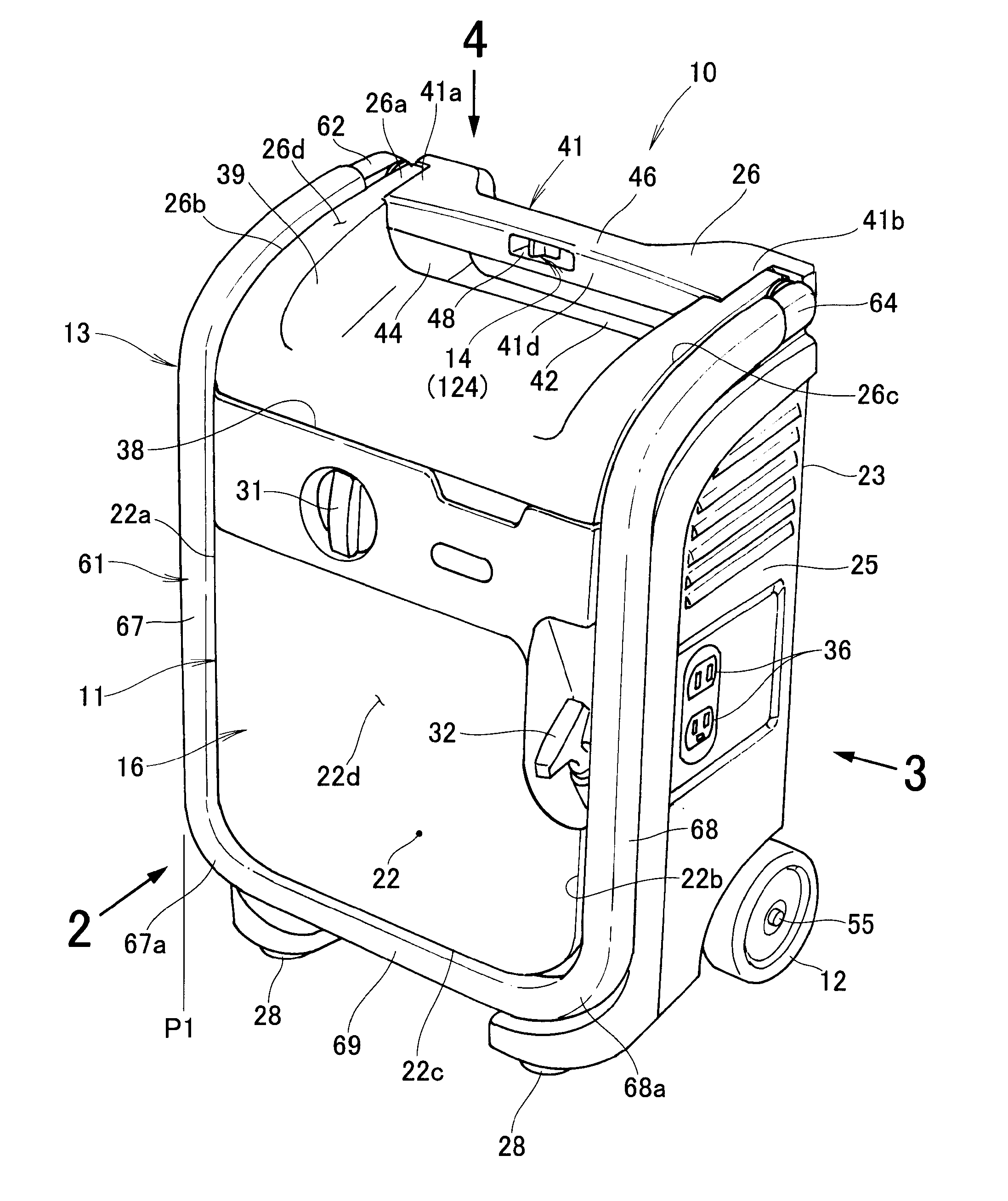
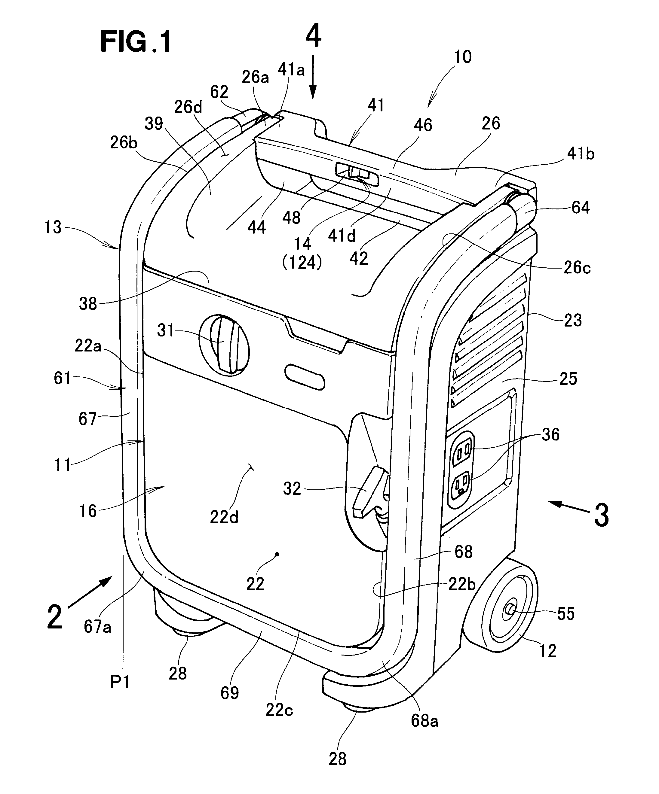
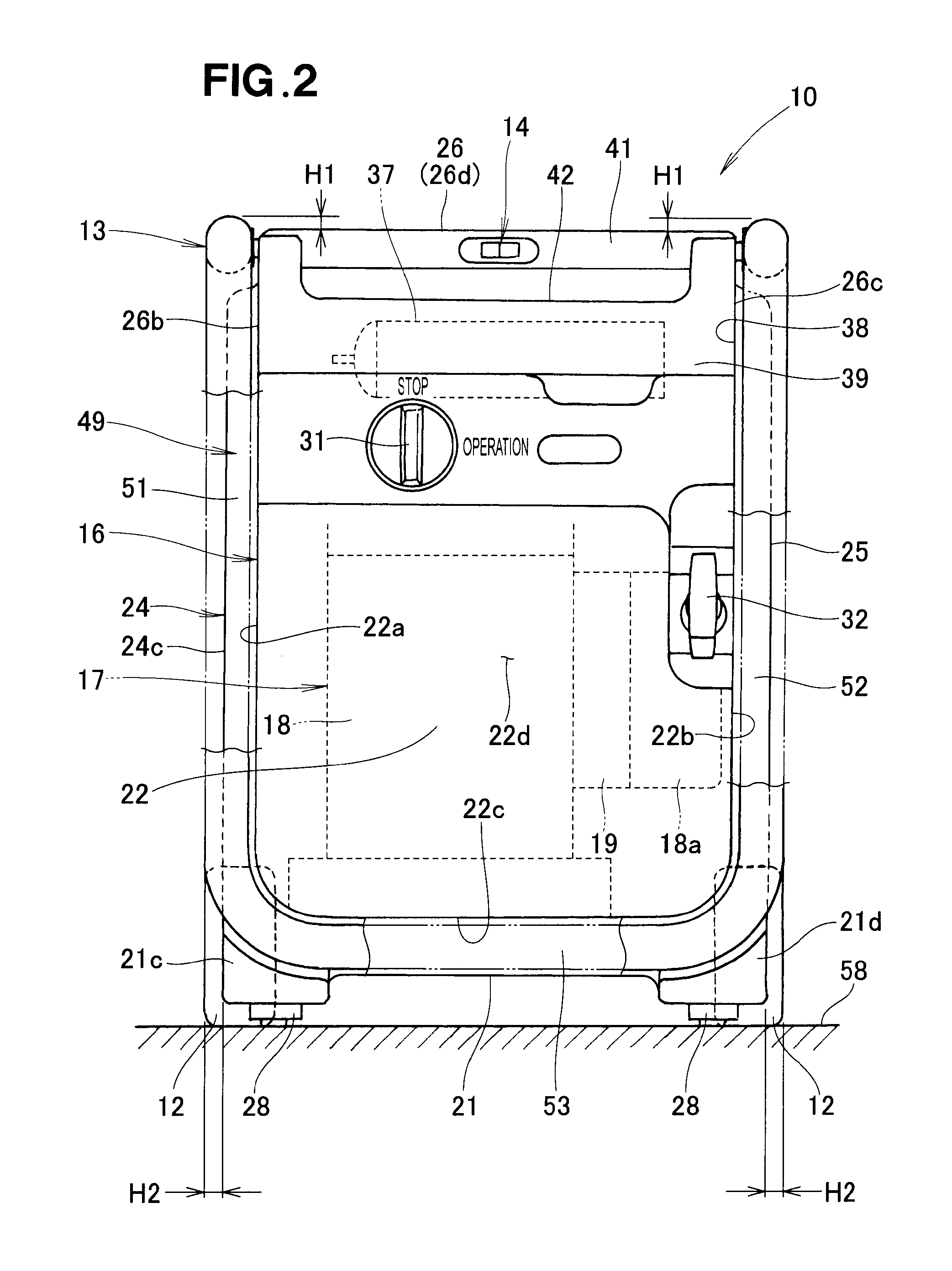
[0034]Reference is now initially to FIG. 1 showing in perspective a working machine 10 having a handle structure 13 (hereinafter referred to also as “working machine handle structure 13”), according to an embodiment of the present invention and to FIG. 2 showing the working machine as seen in the direction of arrow 2 in FIG. 1. In the illustrated example of FIG. 1, the working machine 10 is a portable, towing-type power generator, which includes: a working machine body 11 having a substantially rectangular parallelepiped contour or shape; left and right wheels 12 (the left wheel 12 is shown in FIG. 2) rotatably mounted on the machine body 11; the working machine handle structure 13 pivotably mounted on the machine body 11; and a handle lock structure 14 (see also FIG. 6) for retaining the handle structure 13 in a locked state or position.

[0035]The working machine body 11 includes a case 16 formed in a substantially rectangular parallelepiped shape, and an engine / generator unit 17 pr...


PUM


Abstract

In a working machine, a towing handle is mounted on a top section of a machine body in such a manner that the handle is pivotable between a stored position and a deployed position, and the machine body is towable with the handle in the deployed position. The handle in the stored position extends along outer peripheral portions of the top section and a predetermined wall section of the machine, and the wall section has an upper end region that extends in a machine-towing direction to connect to the top section and has to-be-protected member provided thereon. The handle in the stored position projects outwardly beyond the top section and the wall section.

Description

FIELD OF THE INVENTION[0001]The present invention relates to working machines in which a handle pivotally mounted on the body of a working machine is movable between a stored position where the handle is stored in the machine body and a deployed position where the handle is deployed from the machine body, and in which the machine body is towable by a user or human operator using the handle retained in the deployed position.BACKGROUND OF THE INVENTION[0002]Among the conventionally-known working machines are ones in which the machine body has a substantially rectangular parallelepiped shape and various members, such as an electric outlet and an operation start / stop switch, that need to be protected (i.e., “to be protected members”) are provided on a wall section of the machine body, and in which a towing handle structure (hereinafter referred to also as “working machine handle structure”) is provided on the machine body. As known, for example, from Japanese Patent No. 4167561, the wor...

Claims


Application Information

Patent Timeline
Patent Type & Authority Applications(United States)
IPC IPC(8): B62B5/06B62B1/00
CPCB62B1/00B62B5/067F02B2063/046F02B63/00B62B2205/20B62B1/008B62B1/042B62B2202/48B62B2205/04
Inventor OKABE, KAKU
Owner HONDA MOTOR CO LTD
Why Eureka
Try Eureka