Boundary conduction mode switching regulator and driver circuit and control method thereof

Active Publication Date: 2011-03-10
RICHTEK TECH
View PDF3 Cites 45 Cited by
  • Summary
  • Abstract
  • Description
  • Claims
  • Application Information

AI Technical Summary

Benefits of technology

[0018]In the aforementioned switching regulator or switching regulator driver circuit, in one embodiment, the PWM controller includes an oscillator with an oscillating frequency determined by the control signal. Or, in another embodiment, the PWM controller includes an On-time timer or an Off-time timer which determines the On-time or Off-time of the PWM signal according to the control signal.
[0019]In the aforementioned switching regulator or switching regulator driver circuit, in one embodiment, the control signal generator includes: a capacitor; a charge and discharge circuit, for charging and discharging the capacitor according to the mode signal; a transistor having a controlled end, a current inflow end, and a current outflow end, wherein the controlled end is controlled by the capacitor voltage, and a current is generated at the current inflow end; and a resistor coupled to the current outflow end, wherein the control signal is the current generated at the current inflow end or a voltage at the current outflow end.
[0020]In another embodiment, the control signal generator includes an up/down counter, receiving a clock signal and counting according to the mode signal to generate a count number. The control signal generator may further include a digital to analog converter for converting the count number to an analog signal, and the analog signal may be used as the control signal.
[0021]From yet another perspective, the present invention p

Problems solved by technology

This causes larger switching loss and higher EMI (electro-magnetic interferences), especially in high voltage applications.
In discontinuous conduction mode (DCM) as shown in FIG. 5C,

Method used


Image

  • Boundary conduction mode switching regulator and driver circuit and control method thereof
  • Boundary conduction mode switching regulator and driver circuit and control method thereof
  • Boundary conduction mode switching regulator and driver circuit and control method thereof

Examples


Embodiment Construction

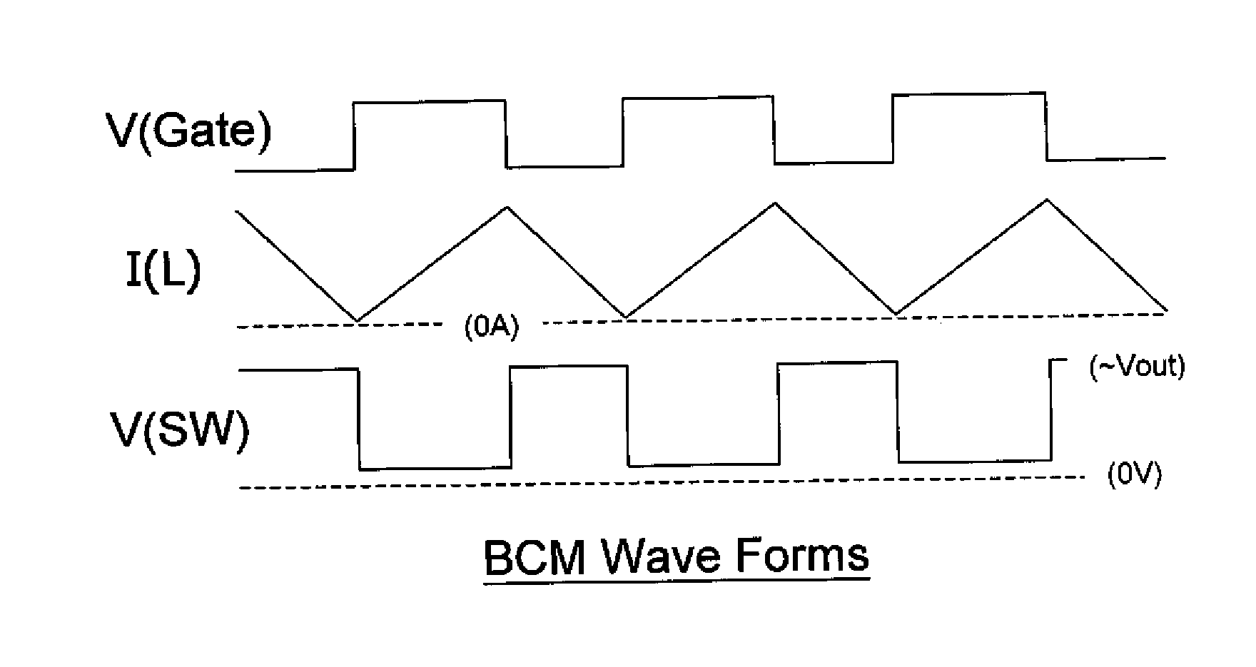
[0044]One key concept of the present invention is to detect the conduction mode of a switching regulator, and to control the switching regulator accordingly such that the switching regulator operates in or near BCM. Thus, the switching loss and EMI can be reduced, and it does not require a high current rating power transistor, so there is less conduction power loss.

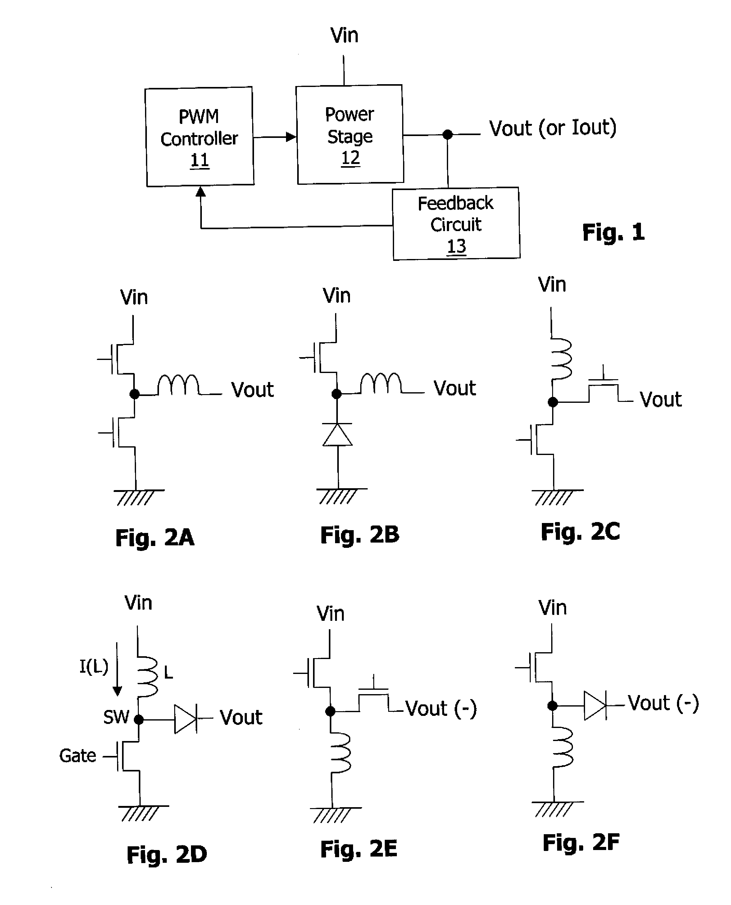
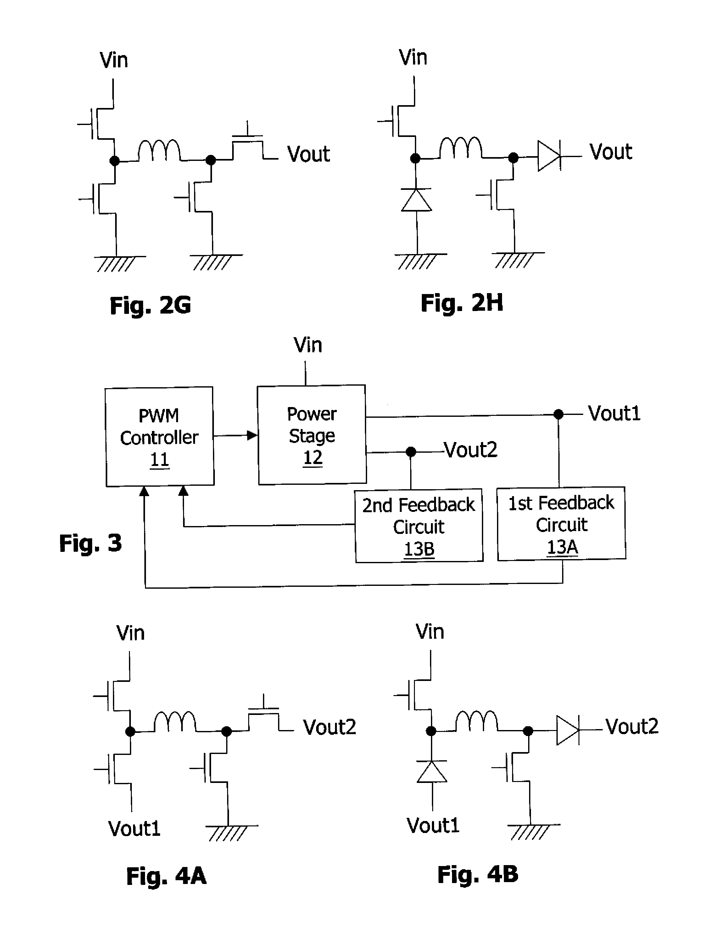
[0045]FIG. 6 shows one embodiment of the present invention. As shown in this figure, the switching regulator of the present invention includes a driver circuit 100, a power stage circuit 12, and a feedback circuit 13. The driver circuit 100 includes a PWM controller 11 which controls at least one power transistor of the power stage circuit 12 to convert an input voltage Vin to an output voltage Vout or output current Iout. The feedback circuit 13 generates a feedback signal relating to the output voltage Vout or the output current Iout and sends the feedback signal to the PWM controller 11 so that the PWM controller 11 ca...


PUM


Abstract

The present invention discloses a boundary conduction mode (BCM) switching regulator, and a driver circuit and a control method of the switching regulator, for controlling a power stage to convert an input voltage to an output voltage or output current. The BCM switching regulator detects whether it is operating in continuous conduction mode (CCM) or discontinuous conduction mode (DCM), and adjusts the On-time, Off-time, or frequency of the power stage accordingly, so that the switching regulator operates in or near BCM.

Description

CROSS REFERENCE[0001]The present invention claims priority to U.S. provisional application No. 61 / 240,057, filed on Sep. 4, 2009.BACKGROUND OF THE INVENTION[0002]1. Field of Invention[0003]The present invention relates to a switching regulator, a switching regulator driver circuit, and a switching regulator control method; particularly, it relates to a switching regulator which is controlled to operate in or near boundary conduction mode (BCM), and a driver circuit and a control method which operate a switching regulator in or near BCM.[0004]2. Description of Related Art[0005]FIG. 1 shows the circuitry of a typical switching regulator, in which a PWM (pulse width modulation) controller 11 controls one or more power transistors in a power stage circuit 12, to convert an input voltage Vin to an output voltage Vout or output current Iout. The power stage circuit 12 may be, but is not limited to, a synchronous or asynchronous buck, boost, inverting or buck-boost converter as shown in FI...

Claims


Application Information

Patent Timeline
IPC IPC(8): G05F1/618
CPCH02M3/156
Inventor LIU, JING-MENG
Owner RICHTEK TECH
Why Eureka
Try Eureka