Computing device

a computing device and small technology, applied in the field of very small computing devices, can solve the problems of not being able to achieve the effect of occupying a very small region of the computing device, clumsy finger operation of the screen, and inability to achieve precise hand motions,

Active Publication Date: 2011-03-10
NAVIGIL
View PDF6 Cites 17 Cited by
  • Summary
  • Abstract
  • Description
  • Claims
  • Application Information

AI Technical Summary

Benefits of technology

[0010]The object is accomplished by dividing the user input operations to spatially separated interface means and detection means and arrange them in a specific configuration in a very near vicinity of the antenna. The interface means may be made available for user interaction and the detection means, which typically comprise dielectric materials, may be safely located b

Problems solved by technology

Smaller size terminals would in many cases be practical but so far it has not been possible to implement very small devices without compromising the comfortable look and feel of the user interface of conventional terminals.
However, in many cases users experience that the finger is too clumsy to operate the screen and they do not wish to carry a stylus for operating the touch screen of the otherwise fully wearable device.
For some users and in some environments very precise hand motions are not even possible.
Many times the operating finger also blocks visibility to the information displayed in the screen, which makes comfortable interaction with menu selections practically impossible.
Using this size of screen simultaneously for both input and output operations is in most of the wearable computer applications not viable.
However, the separation results in that the size of the computing device is the combined size of the screen and the wheel.
For a very small device, like a wrist

Method used


Image

  • Computing device
  • Computing device
  • Computing device

Examples


Embodiment Construction

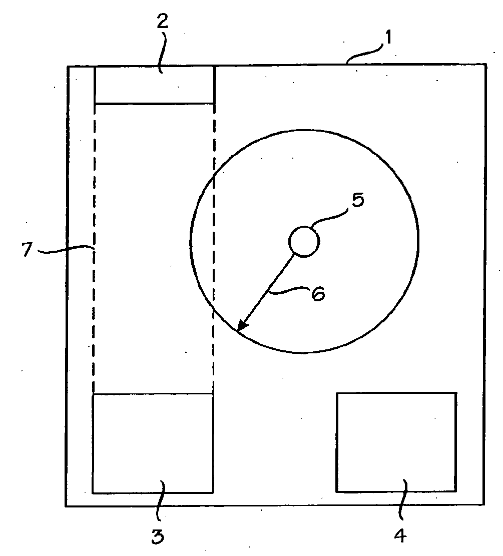
[0023]The following embodiments are exemplary implementations of the present invention. Although the specification may refer to “an”, “one”, or “some” embodiment(s), reference is not necessarily made to and / or a described feature does not apply to only one particular embodiment only. Single features of different embodiments of this specification may be combined to provide further embodiments that are thus considered to belong to the scope of protection. The invention may be applied to any computing device the functions of which are controllable by means of input and output operations. Hereinafter the computing device will be referred to by the term ‘device’. In the following the basic elements of the device will be illustrated with the block chart of FIG. 1. The computing device 1 is a user terminal that comprises a user interface and a radio. In conventional computers the user interface and the antenna of the radio unit are placed far away from each other. This is because the diele...


PUM


Abstract

A computing device (1) includes a controller (4), a radio unit with an antenna (5), detection element (3) and interface element (2). The interface element output, in response to a user actuation, towards detection element (3) a change in a defined physical characteristic. The detection element (3) include dielectric material and are located within the computing device spatially separated from the interface element (2). The detection element (3) is configured to detect the change output by the interface element and output to the controller (4) a signal that corresponds to the change in the defined physical characteristic. The distance from any part of the antenna to a straight line connecting any part of the interface element with any part of the detection element is at some point less than 6 mm.

Description

FIELD OF THE INVENTION[0001]The present invention relates to very small-sized computing devices.BACKGROUND OF THE INVENTION[0002]The demand for small-sized computing devices is continuously increasing. Computing device in this context refers to an apparatus that comprises computer hardware and software required to perform predefined series of arithmetic or logical operations.[0003]For example, in mobile communications the tendency has continuously been towards smaller terminal units. The need for an appropriate match between the size of human fingers and the size of the input keys has, however, by far dictated the dimensioning of the mobile stations. People have generally considered it more important to be able to input keystrokes conventionally with their fingers, even if it means that the device is then bigger and needs to be carried separately in a pocket, a separate supporter or a purse. Smaller size terminals would in many cases be practical but so far it has not been possible ...

Claims


Application Information

Patent Timeline
IPC IPC(8): G06F3/044G06F3/042G06F3/043G06F3/041G06F17/00G04G21/04G04G21/08
CPCG04G21/04H01Q1/273G04G21/08
Inventor RATY, MATTIPUNKKA, EERO
Owner NAVIGIL
Why Eureka
Try Eureka