
Image forming apparatus and control method thereof

a technology of image forming apparatus and control method, which is applied in the direction of visual presentation using printers, digitally marking record carriers, instruments, etc., can solve the problems of image quality deterioration, rendering must be performed, image quality deterioration, etc., and achieve the effect of suppressing print performance reduction and reducing image quality deterioration

Inactive Publication Date: 2011-03-10
CANON KK
View PDF1 Cites 16 Cited by
  • Summary
  • Abstract
  • Description
  • Claims
  • Application Information

AI Technical Summary

Benefits of technology

[0008]The present invention has been made in view of the above-described problems. The present invention provides a technique for reducing image quality deterioration and suppressing print performance reduction in conversion of print data described in a PDL to intermediate data, even in an event of memory overflow that entails fallback processing.
[0010]According to the present invention, it is possible to reduce image quality deterioration and suppress print performance reduction in conversion of print data described in a PDL to intermediate data, even in an event of memory overflow that entails fallback processing.

Problems solved by technology

If lossy-encoding is adopted in the encoding process, image quality deteriorates.
In fallback processing, if lossy-encoding is employed for compressing the entire rendered background image, image quality may deteriorate.
Furthermore, if lossy-encoding is employed on image data of intermediate codes as in the aforementioned prior art, rendering must be performed again.
Moreover, since plural numbers of times of image encoding and decoding may be necessary, print performance reduction is caused.

Method used


Image

  • Image forming apparatus and control method thereof
  • Image forming apparatus and control method thereof
  • Image forming apparatus and control method thereof

Examples


Embodiment Construction

[0022]An embodiment of the present invention will be described hereinafter in detail with reference to the accompanying drawings. Note that the embodiment provides an example in which the present invention is applied to a multi-function peripheral (MFP) as an image forming apparatus.

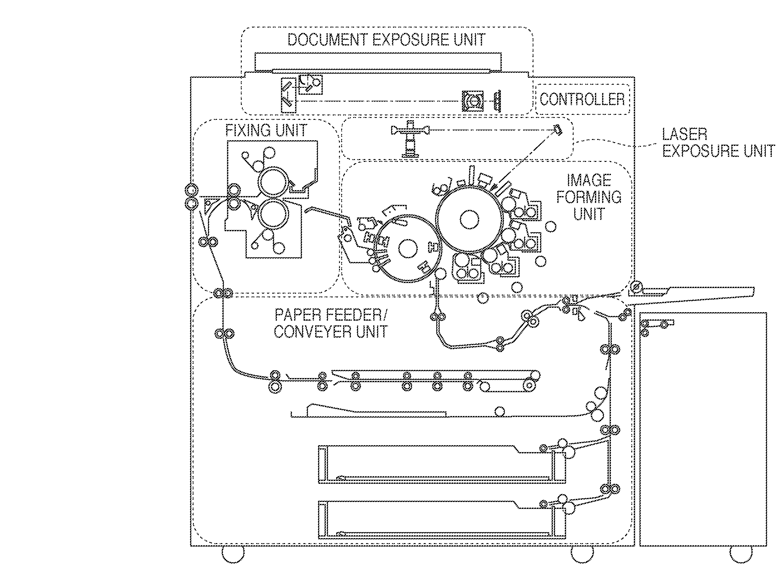
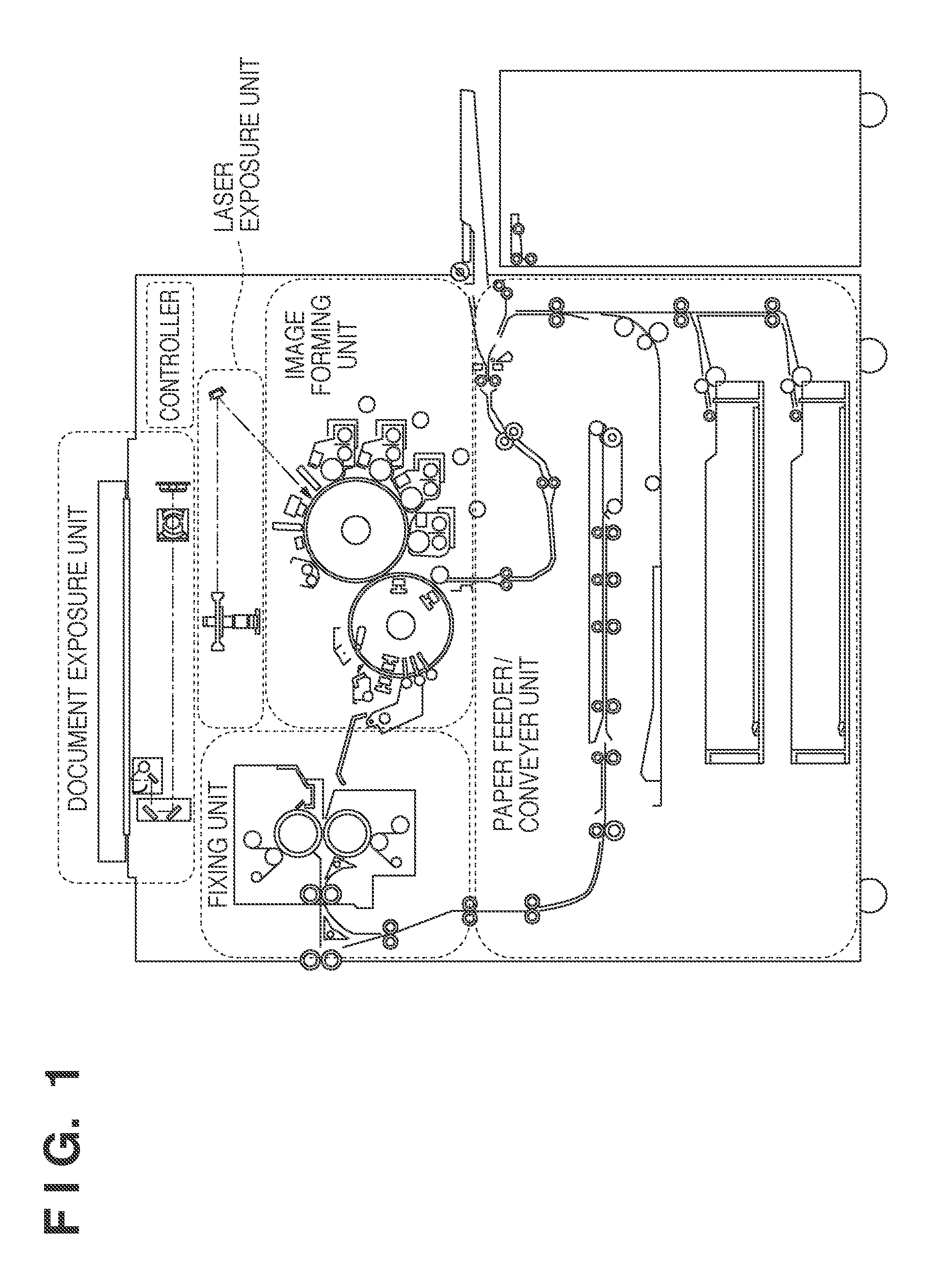
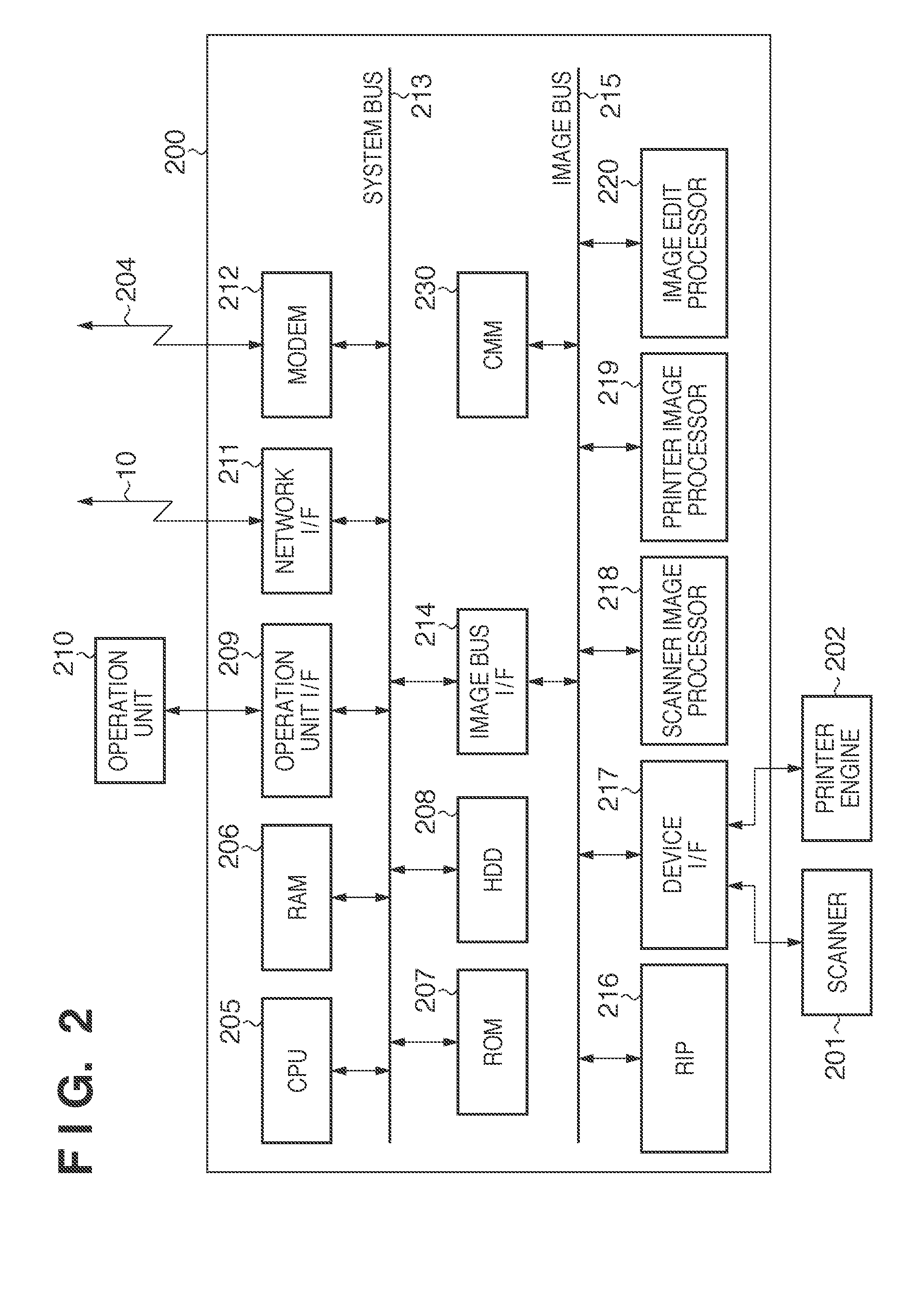
[0023]The MFP according to the present embodiment comprises, as shown in FIG. 1, a controller which controls the overall apparatus, a document exposure unit, a laser exposure unit, an image forming unit, a fixing unit, and a paper feeder / conveyer unit. The document exposure unit irradiates light on an original document placed on a platen for optically reading the original document's image, and converts the image into electric signals for image data generation. The laser exposure unit introduces light beams, such as laser beams modulated in accordance with the image data, to a rotative polygon mirror which rotates at uniform angular velocity, thereby irradiating the light beams as reflective scanning beam...


PUM


Abstract

The present invention provides a technique for reducing image quality deterioration and suppressing print performance reduction. A raster image processor (RIP) generates intermediate data by interpreting PDL data, and stores it in a memory. In a case where the memory area overflows in the middle of intermediate data generation and storage processing on the print data for one page, rendering is executed based on the intermediate data. In accordance with JPEG XR, tile division is performed. An encoding parameter indicative of lossless-encoding or lossy-encoding is determined in accordance with each tile, and encoding is executed. The encoded image data is stored in a background image memory area as a background image of intermediate data that will subsequently be generated. When subsequent intermediate data generation is completed, rendering is executed, the rendered image is synthesized with the image saved as a background image, then the data is outputted.

Description

BACKGROUND OF THE INVENTION[0001]1. Field of the Invention[0002]The present invention relates to an image forming apparatus and a control method of the apparatus.[0003]2. Description of the Related Art[0004]An apparatus having a print function, such as printers, copying machines or the like, interprets print data described in a page description language, converts rendering commands in the print data to intermediate data which is suitable for rendering, and stores the intermediate data in a memory. In accordance with the intermediate data stored in the memory, the apparatus performs processing for bitmap data rendering in a rendering memory. When the apparatus interprets print data and stores intermediate data in a memory, there is a case that the memory becomes full (memory overflow). In this case, the print data interpretation and intermediate data generation are temporarily suspended, and rendering is performed using the intermediate data that has already been stored in the memory...

Claims


Application Information

Patent Timeline
Patent Type & Authority Applications(United States)
IPC IPC(8): H04N1/60
CPCG06K15/02H04N1/32609H04N1/32635G06K15/1863H04N1/41H04N2201/0094H04N2201/3298H04N1/32678
Inventor TOKUMOTO, HIROKAZU
Owner CANON KK
Learn More