Electrowetting pixel structure

a technology of electrowetting and pixel structure, applied in the field of electrowetting pixel structure, can solve the problems of reducing the display quality and the response speed of electrowetting display, and achieve the effect of reducing the delay in contraction, excellent display quality and response speed

Active Publication Date: 2011-03-10
WINTEK CORP +1
View PDF2 Cites 17 Cited by
  • Summary
  • Abstract
  • Description
  • Claims
  • Application Information

AI Technical Summary

Benefits of technology

[0005]In light of the above-mentioned problem, one object of the invention is to provide an electrowetting pixel structure where a non-polar liquid has a reduced delay in contraction to avoid residue left on the edge of the electrowetting pixel structure, and the electrowetting pixel structure has excellent display quality and response speed.

Problems solved by technology

This results in a considerable decrease in the display quality and the response speed of an electrowetting display.

Method used


Image

  • Electrowetting pixel structure
  • Electrowetting pixel structure
  • Electrowetting pixel structure

Examples


Embodiment Construction

[0023]The above and other technical content, characteristics, and functions of the invention will be described in details with reference to the drawings. For clarity, the wording related to direction, such as up, down, left, right, front, back, etc., used in examples is referred to the direction in drawings. Therefore, the wording related to direction is not used to limit the scope of the invention.

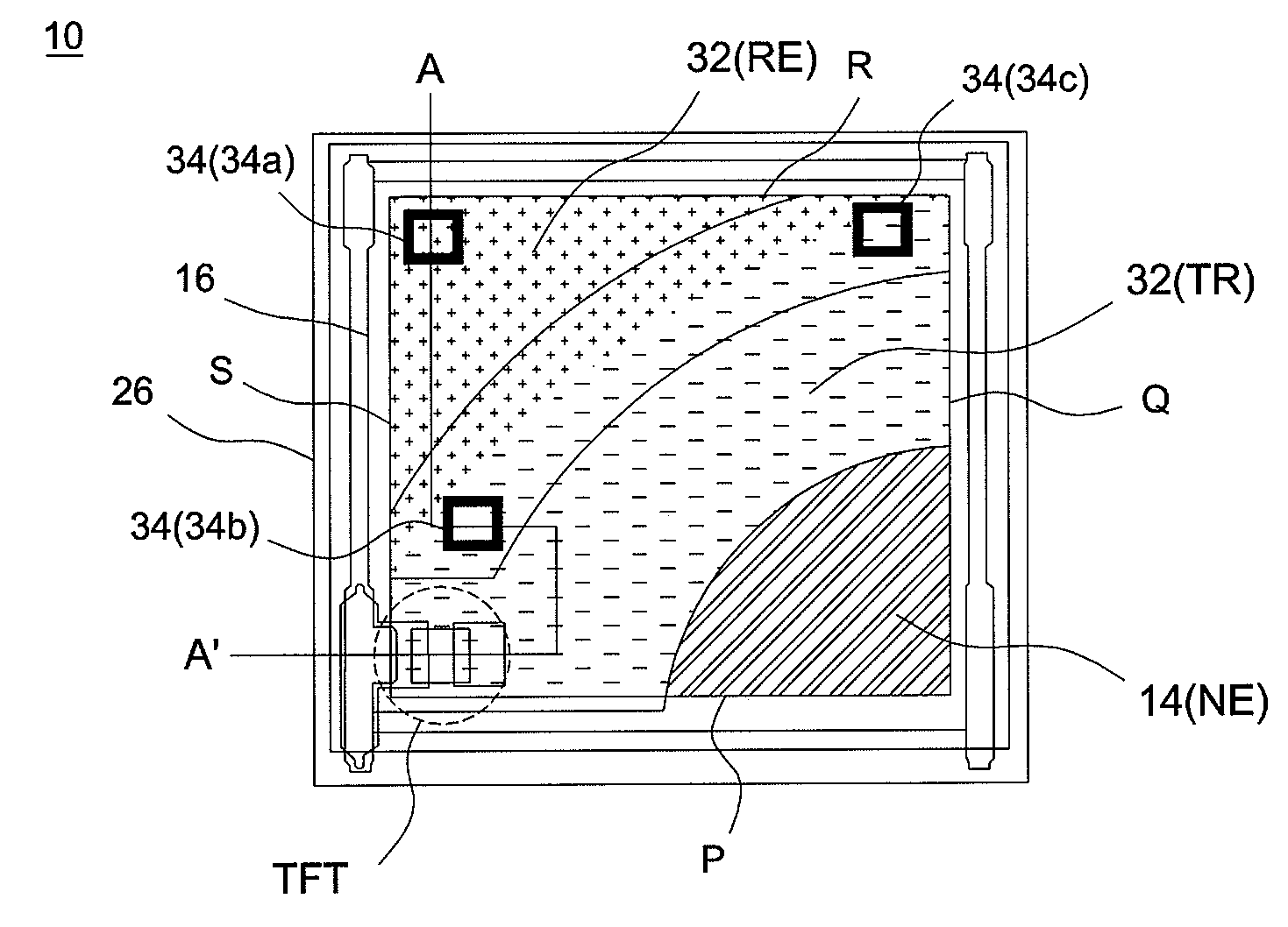
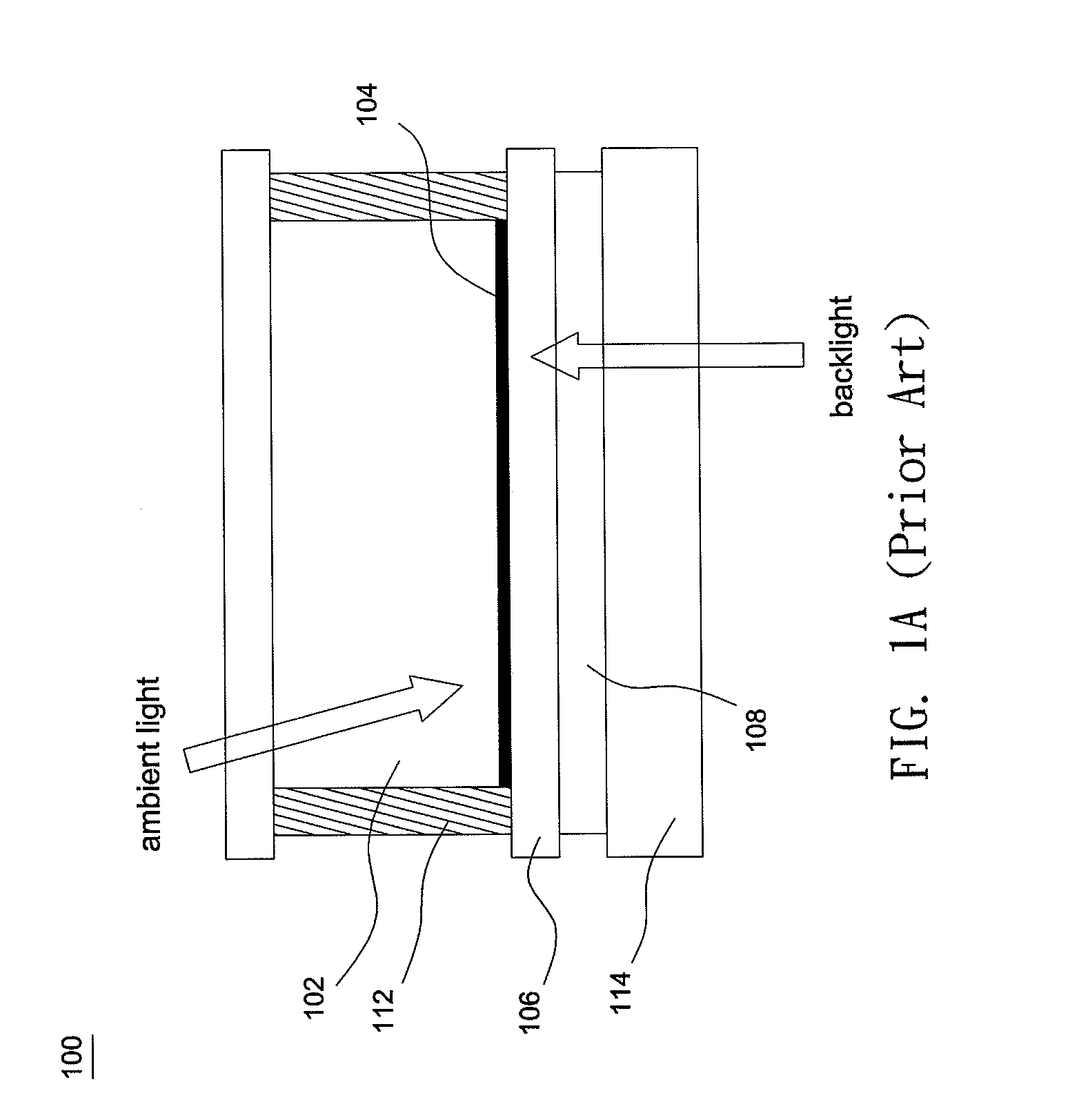
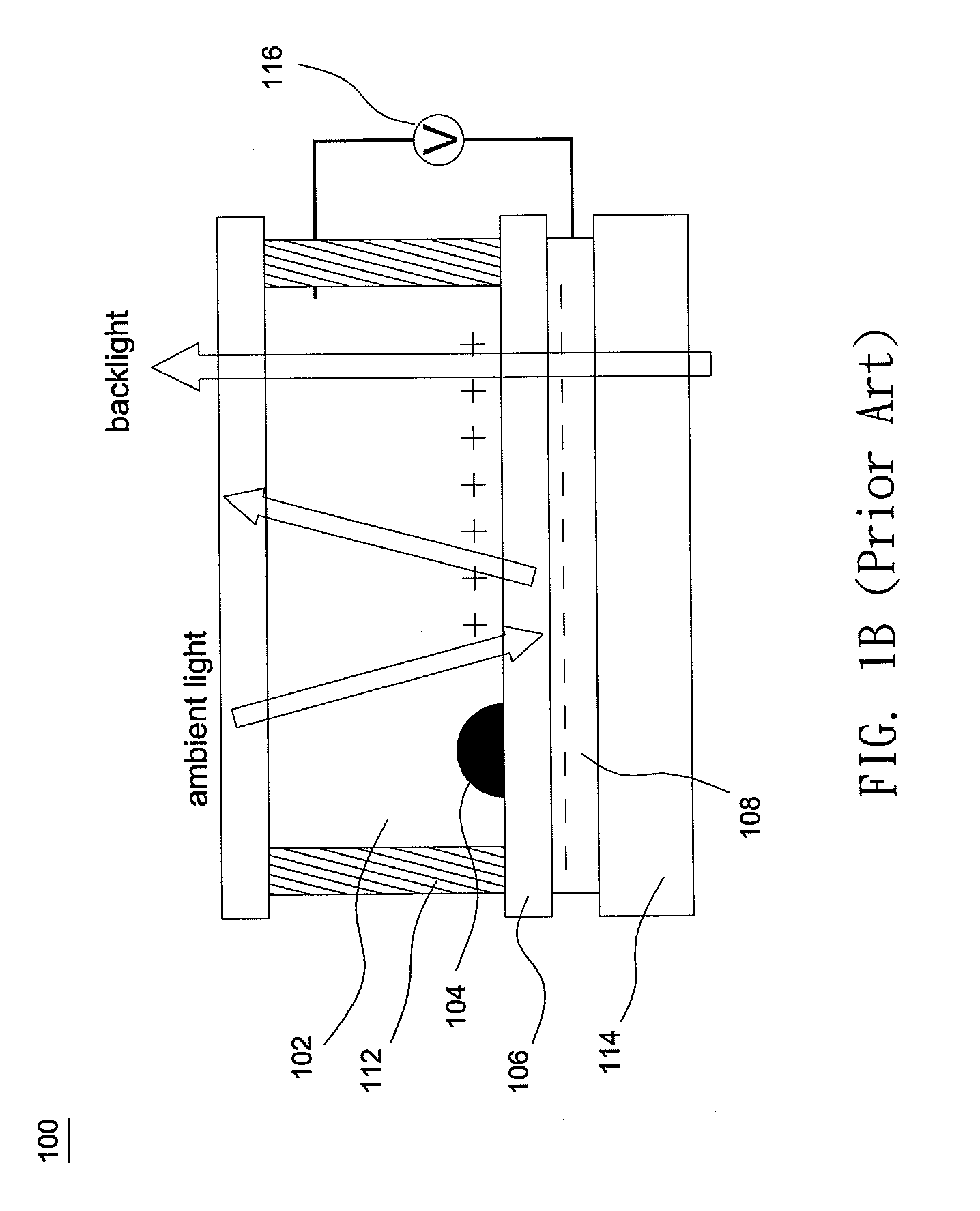
[0024]FIG. 2 shows a cross-sectional schematic diagram illustrating an electrowetting pixel structure according to an embodiment of the invention. As shown in FIG. 2, the electrowetting pixel structure 10 includes a polar liquid 12, a non-polar liquid such as ink 14, and a hydrophobic dielectric layer 16. The ink 14 and the polar liquid 12 are immiscible. When no voltage is applied, the ink 14 evenly covers an upper surface of the hydrophobic dielectric layer 16 and thus ambient light or backlight is absorbed to show a dark state. When a voltage supplied by a voltage source 24 is applied ...


PUM


Abstract

An electrowetting pixel structure includes a substrate, a hydrophobic dielectric layer, a non-polar liquid, a polar liquid, at least one electrode, and at least one contact hole. The hydrophobic dielectric layer is formed on the substrate, the non-polar liquid covers one surface of the hydrophobic dielectric layer, and the polar liquid is provided on the hydrophobic dielectric layer where the non-polar liquid and the polar liquid are immiscible. The electrode is formed on the substrate and divides the substrate into an electrode section and a non-electrode section. When a voltage is applied to the electrowetting pixel structure, the non-polar liquid contracts on the hydrophobic dielectric layer and is confined to an area substantially overlapping the non-electrode section. The contact hole is formed on the substrate at a position away from the non-electrode section of the electrowetting pixel structure.

Description

BACKGROUND OF THE INVENTION[0001](a) Field of the Invention[0002]The invention relates to an electrowetting pixel structure.[0003](b) Description of the Related Art[0004]FIG. 1A and FIG. 1B show cross-sectional schematic diagrams illustrating a display unit 100 of a conventional electrowetting display. As shown in FIG. 1A and FIG. 1B, the display unit 100 includes a polar liquid 102, a black ink 104, and a hydrophobic dielectric layer 106. As shown in FIG. 1A, when no voltage is applied, the black ink 104 evenly covers an upper surface of the hydrophobic dielectric layer 106 and thus ambient light or a backlight is absorbed to show a dark state. On the contrary, as shown in FIG. 1B, when a voltage supplied by a voltage source 116 is applied to a transparent electrode 108, an interface between the hydrophobic dielectric layer 106 and the aqueous solution 102 is polarized to increase surface energy. In that case, the hydrophobic dielectric layer 106 becomes less hydrophobic to push th...

Claims


Application Information

Patent Timeline
Patent Type & Authority Applications(United States)
IPC IPC(8): G02B26/00
CPCG02B26/004
Inventor WANG, SHIH-YUANHAN, HSI-RONGCHAN, CHIEN-TINGTSAI, WAN-JENCHENG, WEI-YUANLO, KUO-LUNG
Owner WINTEK CORP
Why Eureka
Try Eureka