isolator

a technology of isolators and ionizers, which is applied in the direction of measuring fluid loss/gain rate, process and machine control, instruments, etc., can solve the problems of deteriorating work efficiency, workers, etc., and so as to reduce the effect of reducing the time necessary for a sterilizing process

Inactive Publication Date: 2011-03-10
PHC HLDG CORP
View PDF1 Cites 31 Cited by
  • Summary
  • Abstract
  • Description
  • Claims
  • Application Information

AI Technical Summary

Benefits of technology

[0030]According to the present invention, the time necessary for a sterilizing process in an isolator can be further shortened.
[0031]Also, according to the another embod

Problems solved by technology

Therefore, a leak test with high reliability cannot be performed.
In an isolator, if a sterilizing process takes a long time, it also takes a long time before the isolator is in a state where the subsequent work can be started, thereby deteriorating the work efficiency.
Therefore, when performing discharge at a large discharge amount, a process for efficiently reducing the sterilizing substance is not performed in the first half of a substitution step by the equipment (a reduction process unit) fo

Method used


Image

  • isolator
  • isolator
  • isolator

Examples


embodiment 1

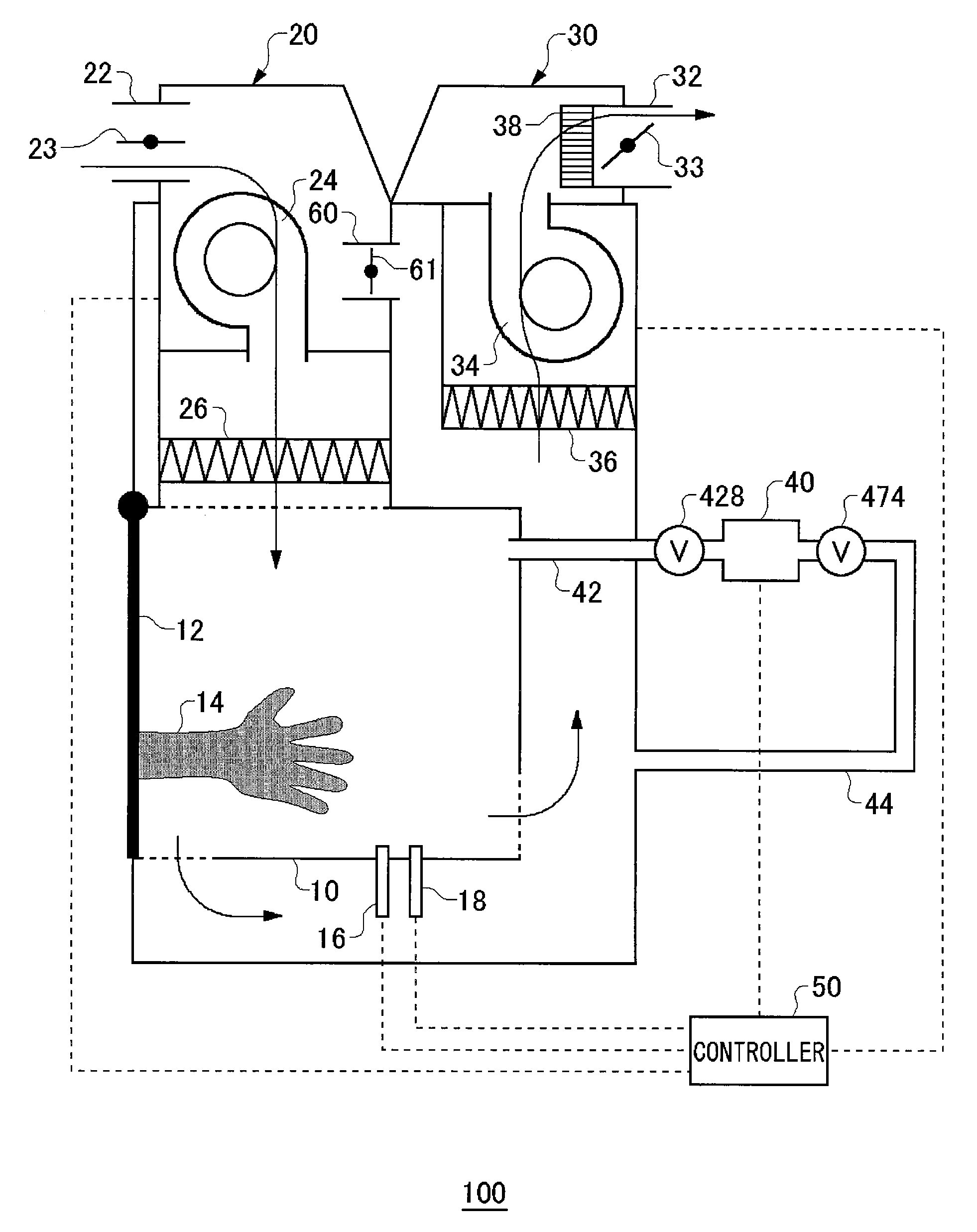
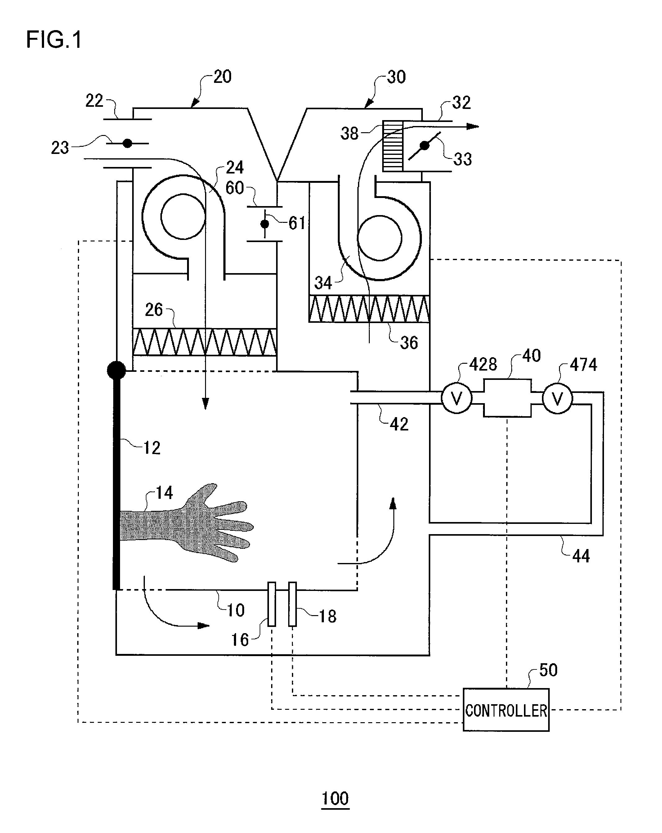
[0103]FIG. 1 is a schematic view illustrating the structure of an isolator 100 according to Embodiment 1.

[0104]As illustrated in FIG. 1, the isolator 100 according to Embodiment 1 comprises a work chamber 10, a gas supply unit 20, a gas discharge unit 30, a sterilizing substance supply unit 40, and a controller 50.

[0105]The work chamber 10 is a space for performing a work in which a biomaterial is handled, such as cell extraction and cell culture. A front door 12 is provided in the work chamber 10 in an openable and closable manner, and work gloves 14 for performing a work within the work chamber 10 are provided at certain positions of the front door 12. A worker can perform, through the work gloves 14, a work within the work chamber 10 after inserting his / her hands from not-illustrated openings that are provided on the front door 12. Herein, the biomaterial means a material that includes a living organism itself including cells, a substance of which a living organism is composed, o...

embodiment 2

[0156]FIG. 6 is a schematic view illustrating the structure of an isolator 1100 according to Embodiment 2. The isolator 1100 according to Embodiment 1 comprises: a work chamber 1010 for performing a work in which a biomaterial is handled, such as cell extraction and cell culture; a gas supply unit 1040 configured to supply a gas into the work chamber 1010; a gas discharge unit configured to discharge the gas in the isolator 1100; a sterilizing substance supply unit 1030 configured to supply a sterilizing substance into the work chamber 1010; and a controller 1090 configured to control these operations. Herein, the biomaterial means a material that includes a living organism itself including cells, a substance of which a living organism is composed, or a substance that is produced by a living organism.

[0157]The gas supply unit 1040 is provided with an intake vent 1042, a three-way valve 1044, and a fan 1046. The open air is taken in through the intake vent 1042. The three-way valve 1...

embodiment 3

[0190]Embodiment 3 is different from Embodiment 2 in the point that the discharge amount is controlled by feedback. Because the structure of the isolator 1100 other than that and the operations in the sterilizing process, etc., are the same as in Embodiment 2, the descriptions will be made with reference to like drawings and be appropriately omitted.

[0191]FIG. 10 is a schematic graph illustrating discharge control according to Embodiment 3. Specifically, in the substitution step, in which feedback is performed, in the isolator 100, the successive changes in the concentration of the hydrogen peroxide gas and the discharge amount are illustrated.

[0192]The concentration of the hydrogen peroxide gas is measured by the concentration measurement unit 1056, which is provided on the gas flow downstream side of the gas discharge unit 1050 (see the lower curve in FIG. 10). The discharge amount of the gas discharge unit 1050 is controlled by increasing / reducing the rotational speed of the fan ...


PUM


Abstract

An isolator includes a work chamber, a sterilizing substance supply unit, a gas flow channel pressure adjustment unit, a work chamber barometer, and a controller. The controller is configured to control execution of a gas flow channel leak test for checking a gas leak in a gas flow channel based on a detection result by the work chamber barometer after making the gas flow channel pressure adjustment unit increase or decrease the pressure in the gas flow channel, and is configured to control supply of the sterilizing substance by the sterilizing substance supply unit. The controller performs heating of a heater, which accompanies the supply of the sterilizing substance, in parallel with the gas flow channel leak test.

Description

FIELD OF THE INVENTION [0001]The present invention relates to an isolator.DESCRIPTION OF THE RELATED ART [0002]An isolator includes therein a work chamber that is under a sterile environment and is used for the work that is performed in a sterile environment in the work chamber, for example, for a work in which a biomaterial is handled, such as cell culture. Herein, the sterile environment means an environment that is as close to a dust-free, sterile environment as possible to prevent contamination of substances other than ones necessary for the work to be performed in the work chamber.[0003]In an isolator, to maintain the sterile environment in the work chamber, a sterilizing process is performed in which a sterilizing substance, such as hydrogen peroxide, is supplied into the work chamber such that the inside of the work chamber is sterilized (see Japanese Patent Application Publications Nos. 2006-68122 and 2005-218548). In the isolator system described in Japanese Patent Applicat...

Claims


Application Information

Patent Timeline
IPC IPC(8): G05D7/00
CPCA61L2/0094A61L2/025A61L2/208A61L2202/11C12M37/00A61L2202/14B01L1/02G01M3/26A61L2202/13A61L2202/122B01L2300/14
Inventor YOKOI, YASUHIKOOHNISHI, JIROIWAMA, AKIFUMIHARADA, MASAKINOGUCHI, YOSHIAKI
Owner PHC HLDG CORP
Why Eureka
Try Eureka