Sole having the tilt surface and the knee joint-protecting shoe comprising the same
- Summary
- Abstract
- Description
- Claims
- Application Information
AI Technical Summary
Benefits of technology
Problems solved by technology
Method used
Image
Examples
first embodiment
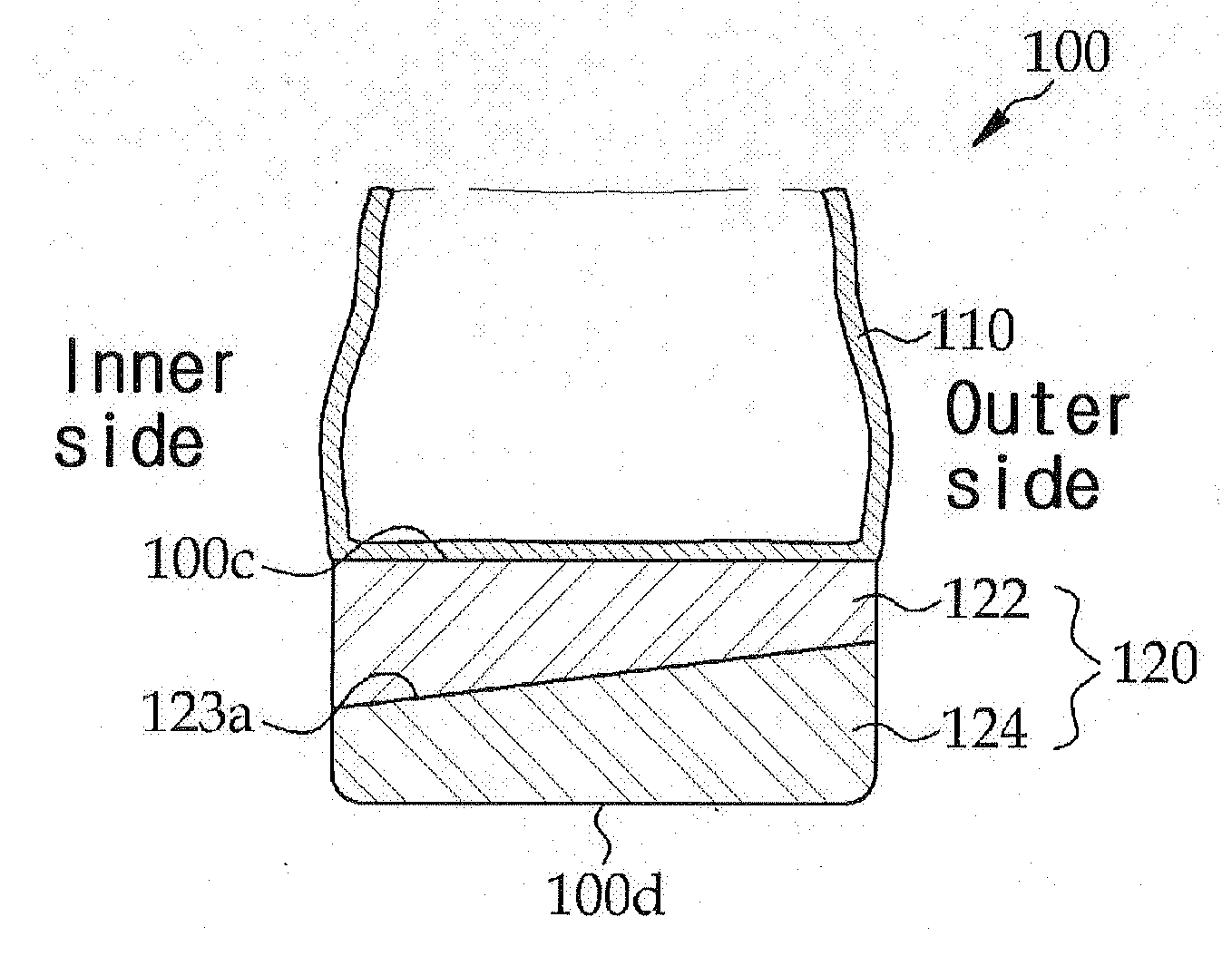
[0083]FIG. 4 is the sectional view in the width direction of the shoe according to the first embodiment of the invention, which is worn by a person with O-shape knee, bow legs. As shown in FIG. 4, a shoe 100 includes the sole 120 and the upper leather 110, and the sole 120 of the shoe 100 is formed as an inclined structure in that it comprises an upper member 122 and a lower member 124 wherein the said two parts 122 and 124 be formed by the tilt surface 123a being split in the width direction. According to the present invention, the sole 120 of the inclined structure is made such that the tilt surface 123a is formed to be tilted toward the inside or outside of the shoe 100 according to an alignment of the skeletons of the lower limbs of the person wearing the shoe 100.
[0084]Here, the top 100c and the bottom 100d of the sole 120 are formed parallel to each other. Furthermore, the lower member 124 is made of a material with hard grade hardness than the material of the upper member 122...
second embodiment
[0087]FIG. 5 is an exploded-sectional view of the sole according to the second embodiment of the invention. As shown in FIG. 5, a sole 120 is advantageously made such that a top surface 100c and a bottom surface 100d of the sole are formed parallel to each other and a deformable member 123 for inducing shear deformation along the sloping surfaces 123a and 123b is arranged between a upper member 122 and a lower member 124 to form an inclined structure. In this case, the deformable member 123 is constructed with a same inclination as in the tilt surfaces 123a and 123b, which divide the upper member 122 and lower member 124. Namely, the shear deformation of deformable member 123 is induced in the direction of the tilt surfaces 123a and 123b by force being exerted from the top surface of the sole 120, thereby acting a moment to the foot of the person wearing with the shoe 100 toward the inner or outer side while sliding the upper member 122 in the direction of the tilt surfaces 123a and...
third embodiment
[0093]FIG. 7 is the rear view of the shoe according to a third embodiment of the invention, and FIG. 8 is a rear view of a state in which a person with O-shaped knee is wearing a shoe illustrated in FIG. 7 and goes on foot. As shown in FIGS. 7 and 8, the inclined structure is designed such that an inner edge 100a of the sole 120 is formed toward an outer edge 100b, or vice versa, the outer edge 100b thereof is tilted toward the inner edge 100a with a certain angle α in order to form a cross section in the width direction of the sole 120 with reverse trapezoidal shape. The angle of inclination α is formed at the edge of the sole 120 which the lowermost part of the sloping surfaces 123a and 123b is formed with the range of 0°<α≦60°.
[0094]As shown in FIG. 7, the sole 120 which consists of the upper member 122, the deformable member 123 and the lower member 124 makes it possible for person with bow legs to wear the shoes having this sole 120 which the lowest part of the sloping surfaces...
PUM
 Abstract
Description
Claims
Application Information
 - R&D
- Intellectual Property
- Life Sciences
- Materials
- Tech Scout
- Unparalleled Data Quality
- Higher Quality Content
- 60% Fewer Hallucinations
Browse by: Latest US Patents, China's latest patents, Technical Efficacy Thesaurus, Application Domain, Technology Topic, Popular Technical Reports.
© 2025 PatSnap. All rights reserved.Legal|Privacy policy|Modern Slavery Act Transparency Statement|Sitemap|About US| Contact US: help@patsnap.com


