
Point forming processes

Active Publication Date: 2011-03-17
THE NAT MASCH CO
View PDF11 Cites 8 Cited by
  • Summary
  • Abstract
  • Description
  • Claims
  • Application Information

AI Technical Summary

Benefits of technology

[0004]The invention involves cold-forming methods and machinery for the economical production of metal parts characterized by a high reduction in area and long length or other substantial change in form while avoiding secondary machining operations. The invention is disclosed in the context of a multi-die progressive former, generally known in the art, and a unique arrangement of dies and tools and related instrumentalities. In preferred embodiments, a long, high carbon steel part is pointed with a reduction in area of about 95% in a net shape or near net shape process. At an intermediate station in the disclosed embodiments, the tooling is arranged to perform a novel closed cavity consequent hydrostatic extrusion process. The tooling and method achieves, in high carbon steels for example, area reductions to

Problems solved by technology

This degree of area reduction effectively results in a pointed workpiece.

Method used


Image

  • Point forming processes
  • Point forming processes
  • Point forming processes

Examples


Embodiment Construction

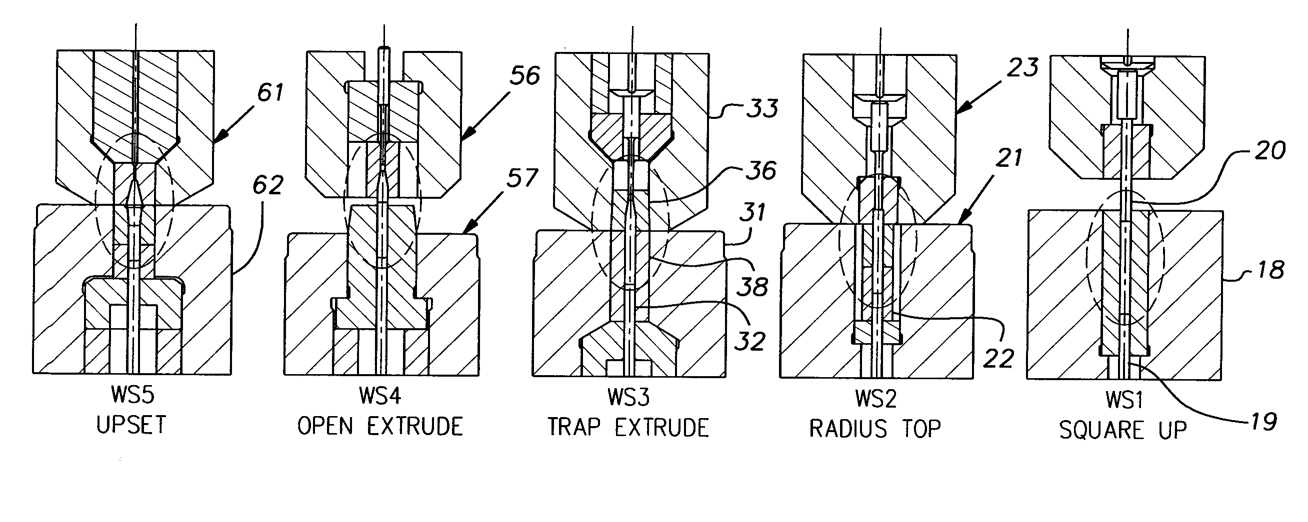
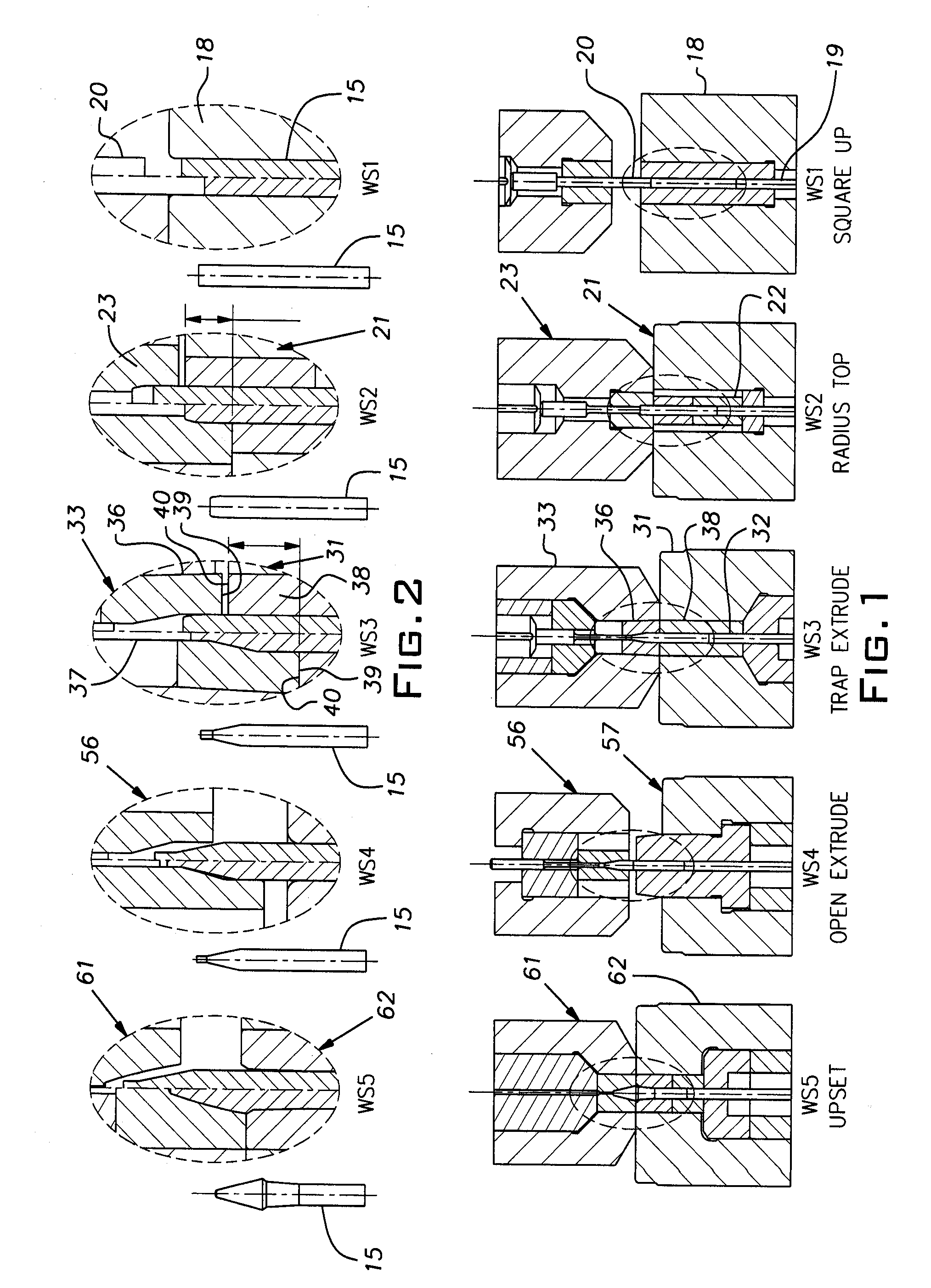
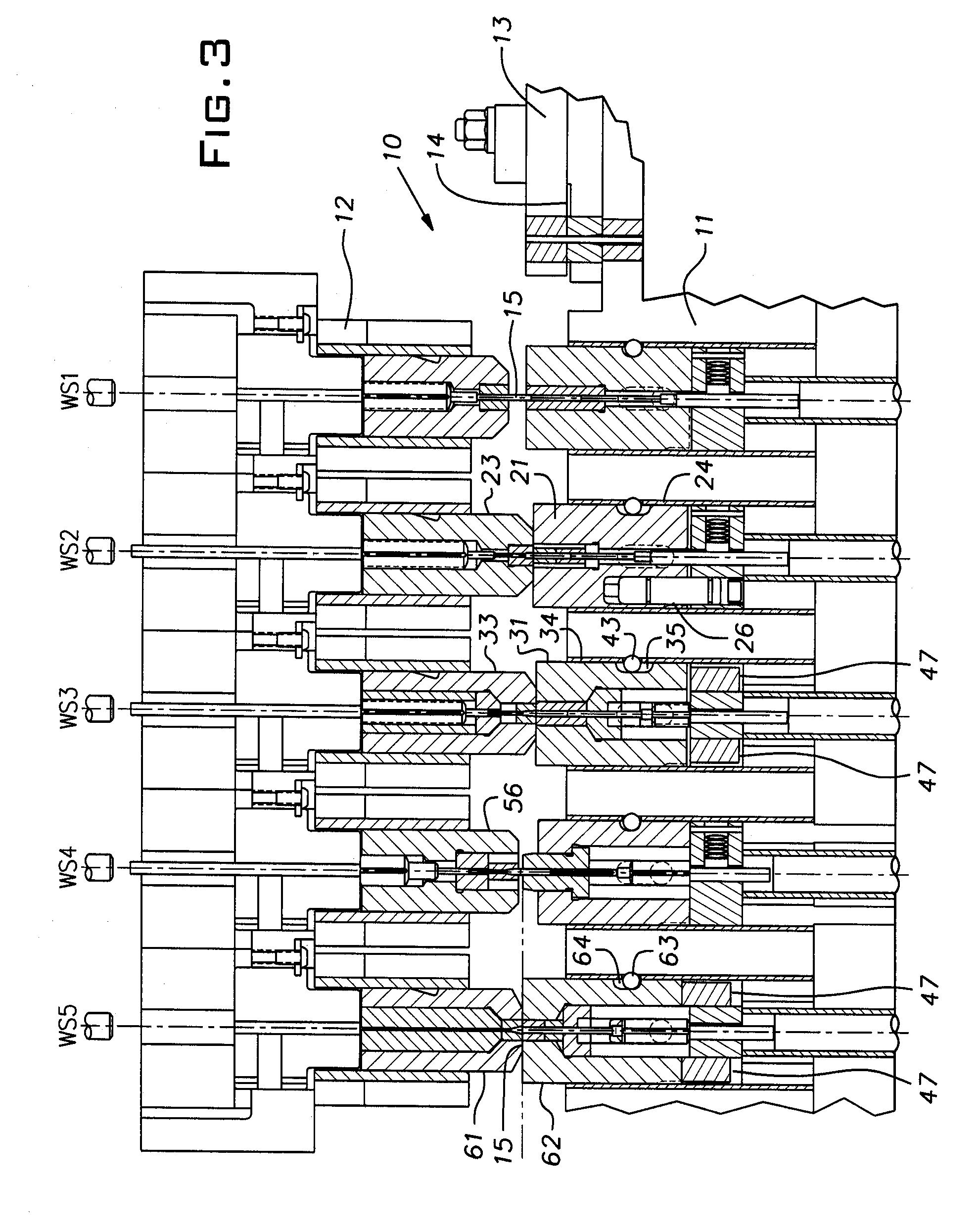
[0017]Referring to FIG. 3, a cold-forming machine 10 includes a die breast or bolster 11 and a slide or ram 12 guided for reciprocation towards and away from the die breast. U.S. Pat. No. 4,898,017, the disclosure of which is incorporated herein by reference, details the general arrangement and is an example of a machine useful in practicing the present invention. The illustrated machine 10 has five forming stations WS1-WS5 downstream of a cutoff station 13. It is conventional to arrange the cutoff station 13 and successive workstations WS1-WS5 in a common horizontal plane each with an equal spacing from adjacent ones of these stations. This permits a generally conventional mechanical transfer device to move a workpiece 15 progressively from one station to the next in a known manner.

[0018]FIG. 3 illustrates certain details of the machine while enlarged details of the forming tools are illustrated in FIGS. 1 and 2. The workstations of FIG. 2 are superposed with the same workstations ...


PUM

PropertyMeasurementUnit
Fractionaaaaaaaaaa
Pressureaaaaaaaaaa
Diameteraaaaaaaaaa

Abstract

A set of tooling for a progressive forming machine comprising die and tool units having internal complementary cavity portions for receiving a workpiece, one of said units being arranged to slide a limited distance along its axis and to be biased by a spring force towards the other unit when the units are mounted in the forming machine, the units each having an end face with a smooth surface finish adapted to press against the smooth surface finish of the end face of the other unit, the end face area of one of the units being relatively small compared to its major cross-sectional area whereby a high contact pressure between the end faces is obtained for a given spring bias force such that extrusion / cooling oil coating a workpiece received in the cavity portions is restrained from leakage from the cavity portions across said end faces during a hydrostatic trapped extrusion of the workpiece in the die and tool units whereby the die and tool units are capable of shaping the workpiece to a degree beyond limits of conventional cold-forming processes.

Description

BACKGROUND OF THE INVENTION[0001]The invention relates to metal cold-forming and, in particular, machine arrangements and methods for achieving a high reduction in area of a workpiece.PRIOR ART[0002]Cold-forming machines are typically used to mass produce shaped parts starting with a cutoff of round metal wire. Blanks or workpieces are sheared from a length of wire after straightening from a coil, positioned in successive stationary dies, and struck by reciprocating tools to change their shape into intermediate and, eventually, finished products. These forming operations can include upsetting where the diameter of the wire blank is increased or extrusion where the diameter is reduced or both upsetting and extrusion. Usually, extrusions are accomplished in a stationary die rather than a reciprocating tool. This technique can be problematic where the workpiece is long, i.e. being several times its diameter in length. In these circumstances, the workpiece can tend to stick in the die. ...

Claims


Application Information

Patent Timeline
IPC IPC(8): B21D39/20
CPCB21J3/00B21J9/022B21C25/02B21C9/00B21C1/32
Inventor KRINTZLINE, DONALD E.HAY, THOMAS E.
Owner THE NAT MASCH CO
Learn More