Unlock instant, AI-driven research and patent intelligence for your innovation.

Valve Lash Setting Process

a valve lash and setting technology, applied in valve arrangements, machines/engines, mechanical equipment, etc., can solve problems such as process problems, reduced fuel combustion efficiency, and gradual degradation of engine performan

Active Publication Date: 2011-03-17
ATLAS COPCO INDAL TECHN AB
View PDF2 Cites 24 Cited by
  • Summary
  • Abstract
  • Description
  • Claims
  • Application Information

AI Technical Summary

Problems solved by technology

Failure to accurately measure valve lash and make necessary adjustments thereto may result in gradual degradation of engine performance and reduced fuel combustion efficiency.
This process can be problematic for various reasons.
For example, measurements taken with feeler gauges are often inaccurate due to inconsistent feeler gauge use from measurement to measurement, especially between different workers.
As another example, if the adjuster screw is inadvertently allowed to move while tightening the lock nut, the lash setting can change defeating the principal objective of the process.
These prior processes although useful, were imprecise, time and labor intensive and only slightly improved on reducing or minimizing the many variations and tolerance stack-ups inherent in the complex mechanical engine system.
The prior processes did not measure or take into account the many mechanical variations and tolerances present in different engines of the same type much less the mechanical variations that occur between individual valve assemblies in a single engine.

Method used


Image

  • Valve Lash Setting Process
  • Valve Lash Setting Process
  • Valve Lash Setting Process

Examples


Embodiment Construction

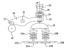
[0020]Examples of a valve lash setting process and a torque device usable therewith are described and illustrated in FIGS. 1-12. Examples of the valve lash setting process described herein can be used on various types of engines. One example of an engine that the process can be used on, and described herein for illustrative purposes, is a diesel engine having a twin-valve arrangement that includes two inlet valves and two exhaust valves for each cylinder. FIG. 1 shows one such pair of valves 11a and 11b of the exemplary diesel engine that can be operated by a cam 10 of an over-head camshaft. The valves 11a and 11b can be biased toward valve seats 12a and 12b by springs 13a and 13b in response to rotation of the cam 10 via a mechanism including a rocker 14 and a yoke 15. The rocker 14 can be pivotally mounted on a spindle 16. The rocker 14 can include a cam follower 17, as well as an adjuster screw 18 and a lock nut 19 at an end opposite the cam follower 17. The adjuster screw 18 can...


PUM


Abstract

A valve lash setting method for setting a predetermined lash in a valve assembly for internal combustion engines. The method includes generating a torque curve and using a linear regression calculation to define a zero crossing point from which a predetermined final lash position of an adjusting screw can be set and secured.

Description

CROSS-REFERENCE TO RELATE APPLICATIONS[0001]This invention claims priority to Provisional Patent Application Ser. No. 61 / 242,036 filed on Sep. 14, 2009 and is incorporated herein by reference in its entirety.BACKGROUND OF THE INVENTION[0002]Accurate adjustment of a clearance between internal combustion engine intake, exhaust, and other valves is important if maximum engine performance and economy are to be obtained. This clearance may also be referred to as “valve lash”. Measuring, adjusting and controlling of valve lash is important to take into account the inherent tolerances and variations in the initial manufacture and assembly of the many mechanical engine components and throughout the life of the engine. Failure to accurately measure valve lash and make necessary adjustments thereto may result in gradual degradation of engine performance and reduced fuel combustion efficiency. Engine manufacturers typically have specific requirements for setting valve lash. For example, an eng...

Claims


Application Information

Patent Timeline
IPC IPC(8): F01L1/18
CPCF01L1/20
Inventor FINKENBINER, MARK ALLEN
Owner ATLAS COPCO INDAL TECHN AB