Facilitating Cooling Of An Electronics Rack Employing Water Vapor Compression System

a technology of water vapor compression and electronic equipment, which is applied in the direction of electrical apparatus casings/cabinets/drawers, domestic cooling apparatus, power cables, etc., can solve the problems of heat generation from electronic equipment, high barrier for recent processor technology, and heat management of data centers, so as to reduce environmental loads, effectively and safely remove heat around the mpu and/or the cpu

Inactive Publication Date: 2011-03-17
IBM CORP
View PDF4 Cites 56 Cited by
  • Summary
  • Abstract
  • Description
  • Claims
  • Application Information

AI Technical Summary

Benefits of technology

[0025]Then, an object of the present invention is to provide an apparatus for making it possible to remove heat around the MPU and / or the CPU effectively and safely without the leak of cooling media such as water while reducing environmental loads caused by computations.
[0027]Still further another object of the present invention is to provide a coolant shielded electronic apparatus for suppressing the heat exhaust from the electronic apparatus to outer environment, in turn, for suppressing power consumption of the data center so as to contribute to global warming.
[0031]The chilled coolant is then circulated through a line extending inside a casing, a rack and / or computing nodes of the electronic apparatus such as, for example, a microcomputer, an enterprise server, a workstation, or a mainframe computer etc. to cool an air flow discharged from the electronic apparatus such that the discharged air flow from the electronic apparatus may not provide severe adverse effects to the air-conditioning capacity in a space such as a computing room in which the electronic apparatus is placed.
[0032]Further according to the present invention, the coolant may be kept under the ambient atmosphere pressure in the region for conducting the heat exchange with the electronic apparatus and may be supported by a flow control member disposed at an up-stream of side of said heat exchange area for settling an un-predictable water leak. Therefore, the possibility of a coolant leak may be minimized.

Problems solved by technology

In nowadays, operations of the electronic apparatuses in a high performance and a high clock rate are increasingly requested yet and then, the heat generation from the electronic apparatuses rises an old but yet new problem in the computing technology.
The problem is the heat generation of the MPU and / or the CPU and there is a technical prediction that a density of the heat generation of a recent MPU with which the operation clock rate is at about several Giga-Hertz goes over that of an atomic reactor and should reach to the heat generation density of sun in near future.
One strategy to reduce the heat generation problem is to make the MPU and / or the CPU in multi-core architectures so as to reduce instructions per a single core while maintaining an overall performance; however, as the clock rate for the single core goes higher and higher with respect to performance improvements, the trade-off problem between the heat exhaust and processor performance will make a high barrier for the recent processor technology.
Such data center tends to develop the computing performance thereof for addressing to increasing demands for high performance computations so that heat management of the data center becomes a serious problem to be settled urgently in relation to global warming due to the computation as well as reduction of investment costs for the data center.
As described above, the water cooling architecture is regarded as suitable for the cooling architecture of the electronic apparatus; however, it is known that water has potential defects for causing an electronic leak when the water immerses into the electronic apparatus.
When the water is leaked in the enclosure of the electronic apparatus, the electric apparatus or facilities such as a data center would suffer huge and high cost damages.
Although attempts for improving hazardous water leak from the cooling system of the electronic apparatus have been made, corrosion mechanisms of lines etc. are not yet understood sufficiently.
Thus, the protection from the problems caused by the corrosion under various conditions is not yet practically ensured, because the corrosions and their magnitudes substantially depend on particular environments in which the electronic apparatuses are placed.
In addition, factors for causing the water leak may include, other than the corrosion, for example, cracks or damages by impacts as well as loosed joint connections such that it is difficult to settle the above various factors and to overcome the adverse effects when all of the above factors are considered.

Method used


Image

  • Facilitating Cooling Of An Electronics Rack Employing Water Vapor Compression System
  • Facilitating Cooling Of An Electronics Rack Employing Water Vapor Compression System
  • Facilitating Cooling Of An Electronics Rack Employing Water Vapor Compression System

Examples


Embodiment Construction

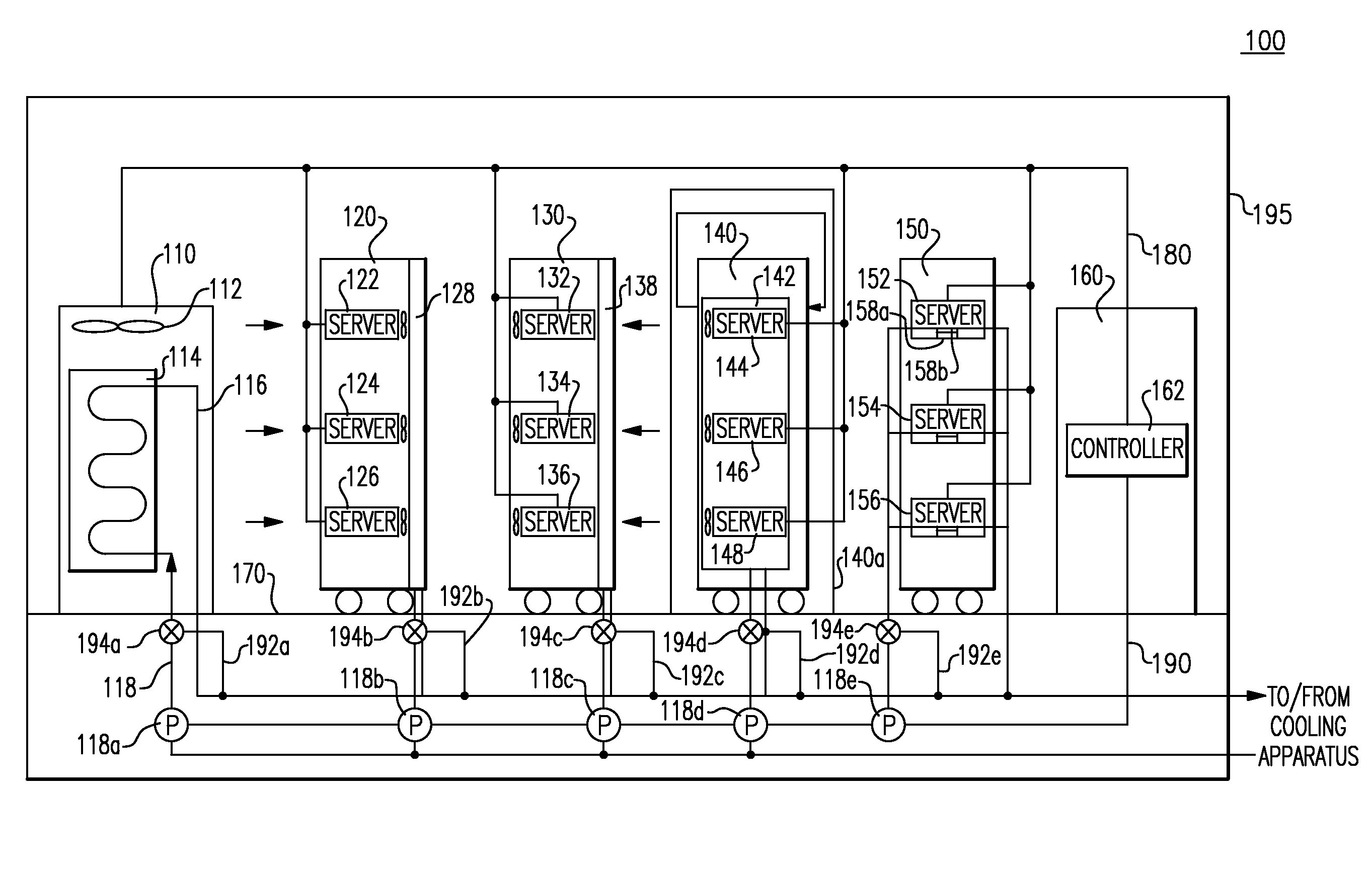
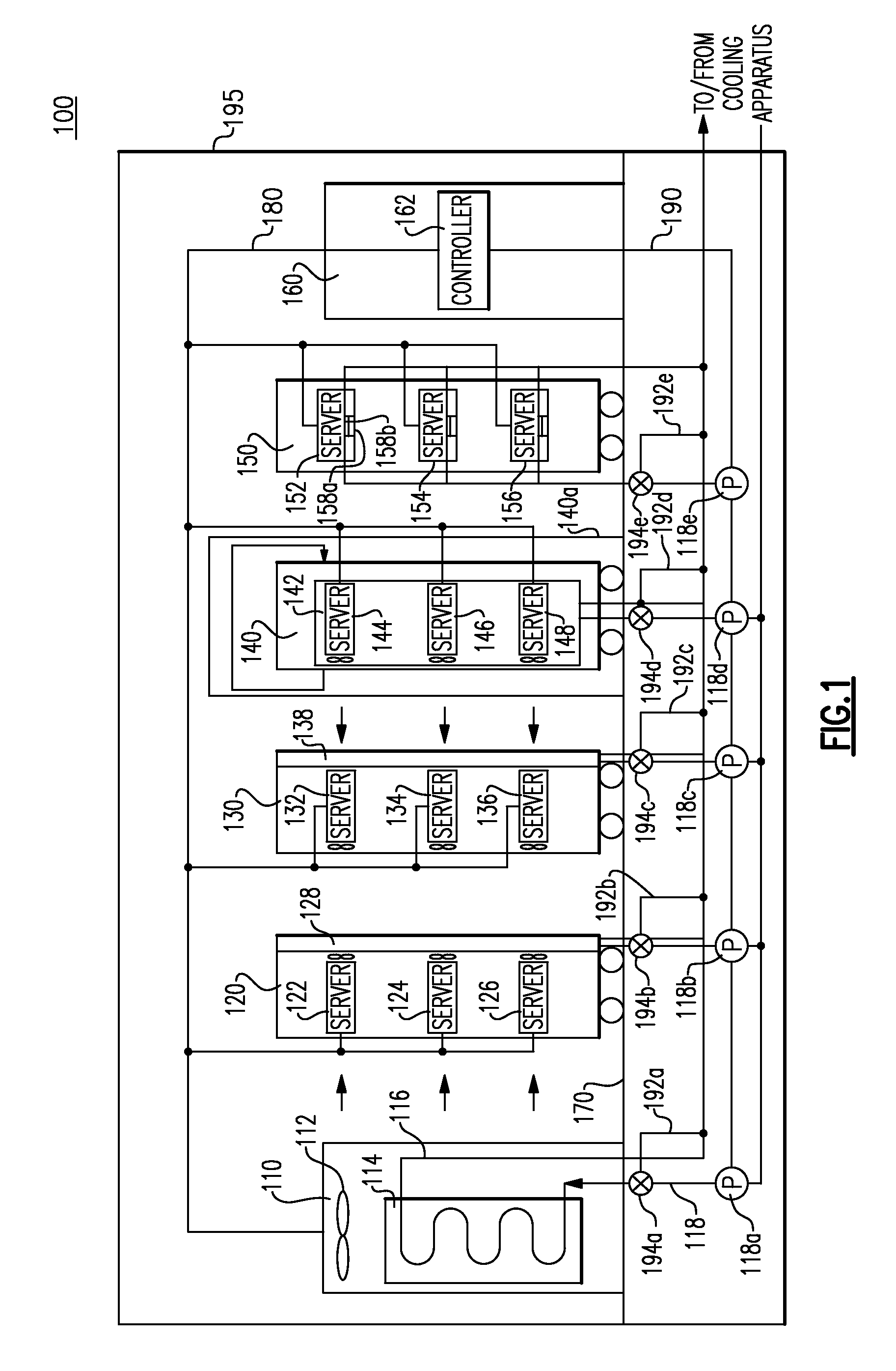
[0059]FIG. 1 generally shows a data center control system with which an apparatus, a method, and a shielded electronic apparatus are implemented. The data center control system 100 comprises a CRAC 110, a plurality of electronic apparatuses 120-150, and an automated environment monitoring facility (hereafter referred to AOEMF) 160. The above apparatuses are placed on a floor panel 170 offset from a floor slab plate to form a space for utility lines. The floor panel 170 may have a perforated section to introduce the chilled air supplied through the space.

[0060]The CRAC 110 conducts an air condition in the computing room 195 as well as the heat management of the apparatuses in the computing room 195. The CRAC 110 receives chilled coolant through a supply line 118 from a building backbone air conditioning system. The air in the computing room 195 is introduced into the CRAC 110 by a fan 112 and is returned into the computing room 195 after the heat exchange at the heat exchanger 114.

[0...


PUM


Abstract

A cooling apparatus and method are provided for facilitating cooling of an electronic apparatus that includes a semiconductor element. The cooling apparatus includes an evaporator containing a coolant and evaporating the coolant under a reduced pressure lower than an ambient pressure to generate a chilled coolant, a condenser regenerating the coolant from a vapor of the coolant and being fluid-communicated with the evaporator through a bypass line, and a circulating pump and a line supplying the chilled coolant to a heat exchange area of the electronic apparatus to conduct a heat exchange with an air flow passing though the semiconductor element at a hot side of the electronic apparatus and returning the coolant after the heat exchange to the condenser.

Description

CROSS-REFERENCE TO RELATED APPLICATION[0001]This application claims the priority benefit under 35 U.S.C. §119 of Japanese application 2008-240689, filed Sep. 19, 2008, and incorporated herein by reference.BACKGROUND OF THE INVENTION[0002]1. Field of the Invention[0003]The present invention relates to water cooling of an electronic apparatus and more particularly, the present invention relates to an apparatus and a method for cooling electronics, a coolant shielded electronic apparatus, and a method for cooling electronics.[0004]2. Description of the Related Art[0005]An electronic apparatus including such as a personal computer, a server, a workstation and / or a mainframe computer typically requires a cooling device for cooling a heat source such as a microprocessor unit (hereafter referred to MPU) or a central processing unit (hereafter referred to CPU) to maintain stable performance thereof. In nowadays, operations of the electronic apparatuses in a high performance and a high clock...

Claims


Application Information

Patent Timeline
Patent Type & Authority Applications(United States)
IPC IPC(8): G06F1/20F28D15/00
CPCG06F1/20H05K7/20827G06F2200/201
Inventor SCHMIDT, ROGER R.TAKAYOSHI, JYUNJITSUKAMOTO, TAKESHIFUNATSU, MASAYOSHIONAI, MINORUIMAI, MASAAKIINOUE, YOSHINORI
Owner IBM CORP
Why Eureka
Try Eureka