Stage lighting fixture and method of operating a stage lighting fixture

a technology of stage lighting and lighting fixtures, which is applied in the field of stage lighting, can solve the problems of wide, but somewhat limited, range of lighting effects, and devices normally featured in lighting fixtures are unsuitable for projecting variable-sized shapes other than convex polygons, and achieve the effect of widening the range of lighting effects

Active Publication Date: 2011-03-17
CLAY PAKY
View PDF7 Cites 21 Cited by
  • Summary
  • Abstract
  • Description
  • Claims
  • Application Information

AI Technical Summary

Benefits of technology

[0009]It is an object of the present invention to provide a stage lighting fixture, and a metho

Problems solved by technology

Known lighting fixtures provide for a fairly wide, but somewhat limited, range of lighting effects.
For example, the devic

Method used


Image

  • Stage lighting fixture and method of operating a stage lighting fixture
  • Stage lighting fixture and method of operating a stage lighting fixture
  • Stage lighting fixture and method of operating a stage lighting fixture

Examples


Embodiment Construction

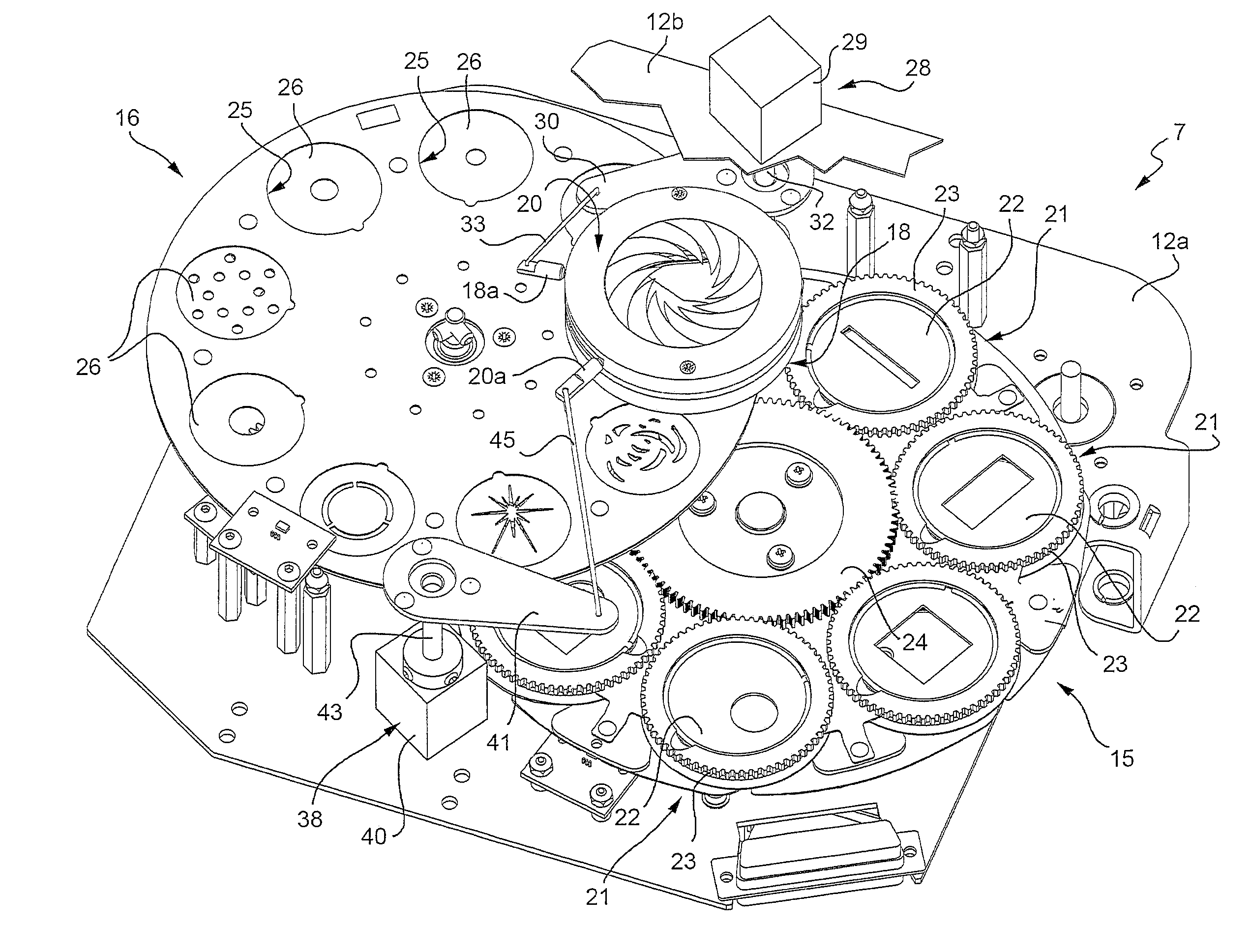
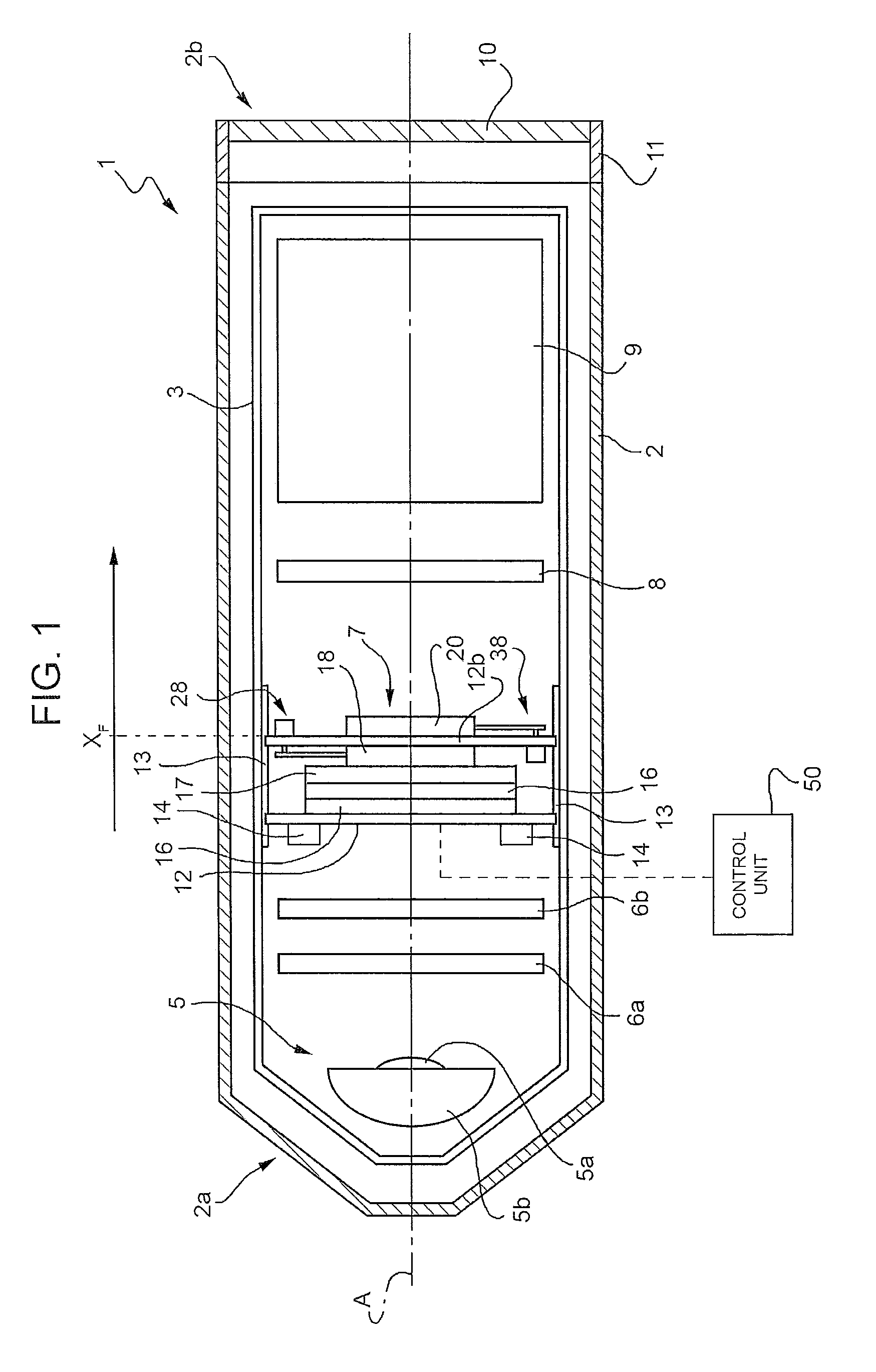
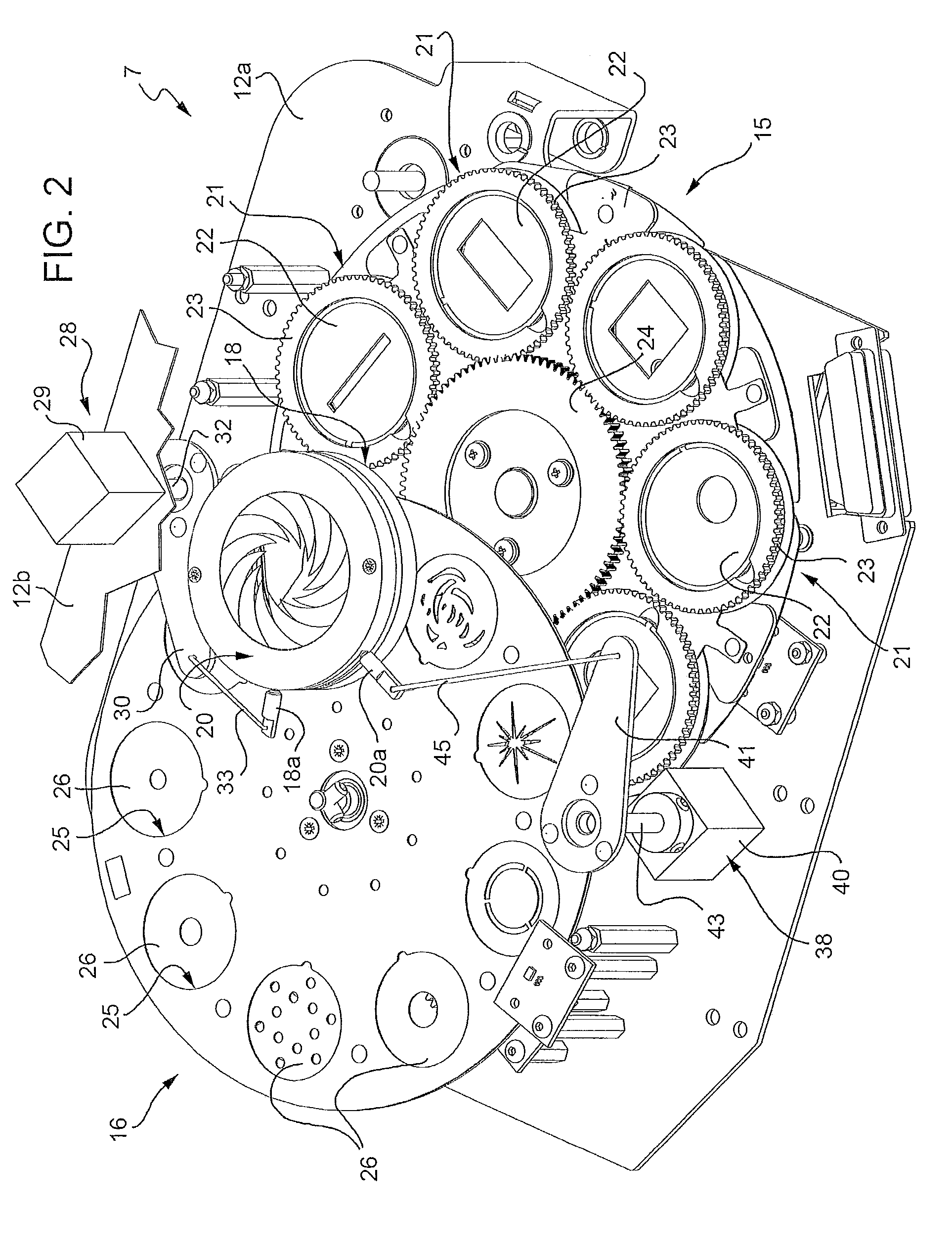
[0016]Number 1 in FIG. 1 indicates as a whole a stage lighting fixture, which comprises a casing 2 extending along a longitudinal axis, and having a closed first end 2a, and an opposite open second end 2b. On a frame 3, casing 2 houses a light source 5, fixed lighting effect devices 6a, 6b, a movable lighting effect assembly 7, a beam splitter 8, a zoom assembly 9, and an objective lens 10, which are arranged successively along an optical axis A substantially coincident with the longitudinal axis of casing 2.

[0017]Lighting fixture 1 is also equipped with a control unit 50, which, in the embodiment described, is located outside casing 2 and designed to control light source 5, fixed lighting effect devices 6a, 6b, movable lighting effect assembly 7, beam splitter 8, and zoom assembly 9.

[0018]Light source 5 is located close to the closed first end 2a of casing 2, and comprises a lamp 5a, and a parabolic or elliptic reflector 5b designed to form the light from lamp 5a into a light beam ...


PUM


Abstract

A stage lighting fixture has a casing having a closed first end and an open second end; a light source housed inside the casing, close to the first end, to emit a light beam along an optical axis oriented longitudinally with respect to the casing; an objective optical system located along the optical axis, at the second end of the casing, and having a focus position; a circular-aperture diaphragm located along the optical axis, between the light source and the objective optical system, to intercept the beam; and an iris diaphragm located along the optical axis, between the light source and the objective optical system, and which can be set to the focus position.

Description

[0001]The present invention relates to a stage lighting fixture, and to a method of operating a stage lighting fixture.BACKGROUND OF THE INVENTION[0002]As is known, a stage lighting fixture comprises a casing housing a light source, beam filtering and profiling means, and an objective lens.[0003]The casing extends along a longitudinal axis, is open at one end, and is closed at the opposite end, where the light source is located. In actual use, the light source, e.g. a halogen lamp, emits a beam substantially along the optical axis of the lighting fixture, which normally coincides with the longitudinal axis of the casing.[0004]The beam filtering and profiling means are located between the light source and the objective lens to intercept the beam, are designed to produce special beam effects, and comprise, for example, beam colouring assemblies, a diaphragm, a number of gobos, and other lighting effect devices.[0005]The diaphragm comprises a plurality of movable leaves fitted to an an...

Claims


Application Information

Patent Timeline
IPC IPC(8): F21V17/02F21V5/00
CPCF21V11/10F21W2131/406F21V14/08
Inventor QUADRI, PASQUALECAVENATI, ANGELO
Owner CLAY PAKY
Why Eureka
Try Eureka