
Device and method for measuring location of terminal

Inactive Publication Date: 2011-03-17
ELECTRONICS & TELECOMM RES INST
View PDF3 Cites 22 Cited by
  • Summary
  • Abstract
  • Description
  • Claims
  • Application Information

AI Technical Summary

Benefits of technology

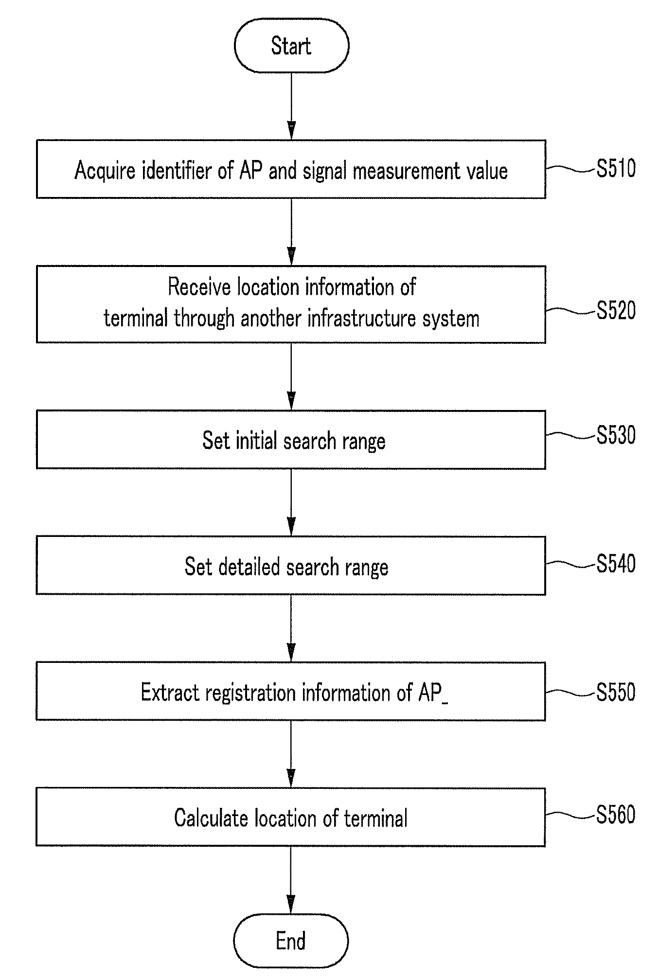
[0010]The present invention has been made in an effort to provide a terminal location determining device and method for reducing time used for searching a database.
[0013]According to an embodiment of the present invention, registration information on the AP needed for measuring the location of the terminal can be quickly acquired from the database by reducing a search range in the database, and unneeded calculation can be reduced, thereby reducing the time for measuring the location of the terminal. Also, location accuracy can be improved.

Problems solved by technology

On the contrary, in the case of the urban areas that is a non-line of sight area, the error of location information is substantially 50 meters because of multipath errors, and particularly, in the case of a room, received signal sensitivity is deteriorated such that the GNSS cannot determine a location.
However, since accuracy of location determination depends on how the base station is disposed and the error of location information is 100 to 800 meters on the average, it is inappropriate for indoor and exterior navigation service requiring location accuracy.
However, when the service area is enlarged and the database is built in a vast manner, it is required to compare the identifier of the AP for the measured value and the identifier of all the AP's of the database, and hence, it takes much time to search the database, location calculation is resultantly slowed, and it is inappropriate for a service that requires a quick response.

Method used


Image

  • Device and method for measuring location of terminal
  • Device and method for measuring location of terminal
  • Device and method for measuring location of terminal

Examples


Embodiment Construction

[0020]In the following detailed description, only certain exemplary embodiments of the present invention have been shown and described, simply by way of illustration. As those skilled in the art would realize, the described embodiments may be modified in various different ways, all without departing from the spirit or scope of the present invention. Accordingly, the drawings and description are to be regarded as illustrative in nature and not restrictive. Like reference numerals designate like elements throughout the specification.

[0021]Throughout the specification and claims, unless explicitly described to the contrary, the word “comprise” and variations such as “comprises” or “comprising” will be understood to imply the inclusion of stated elements but not the exclusion of any other elements.

[0022]A method and device for measuring a location of a terminal according to an exemplary embodiment of the present invention will now be described with reference to accompanying drawings.

[00...


PUM


Abstract

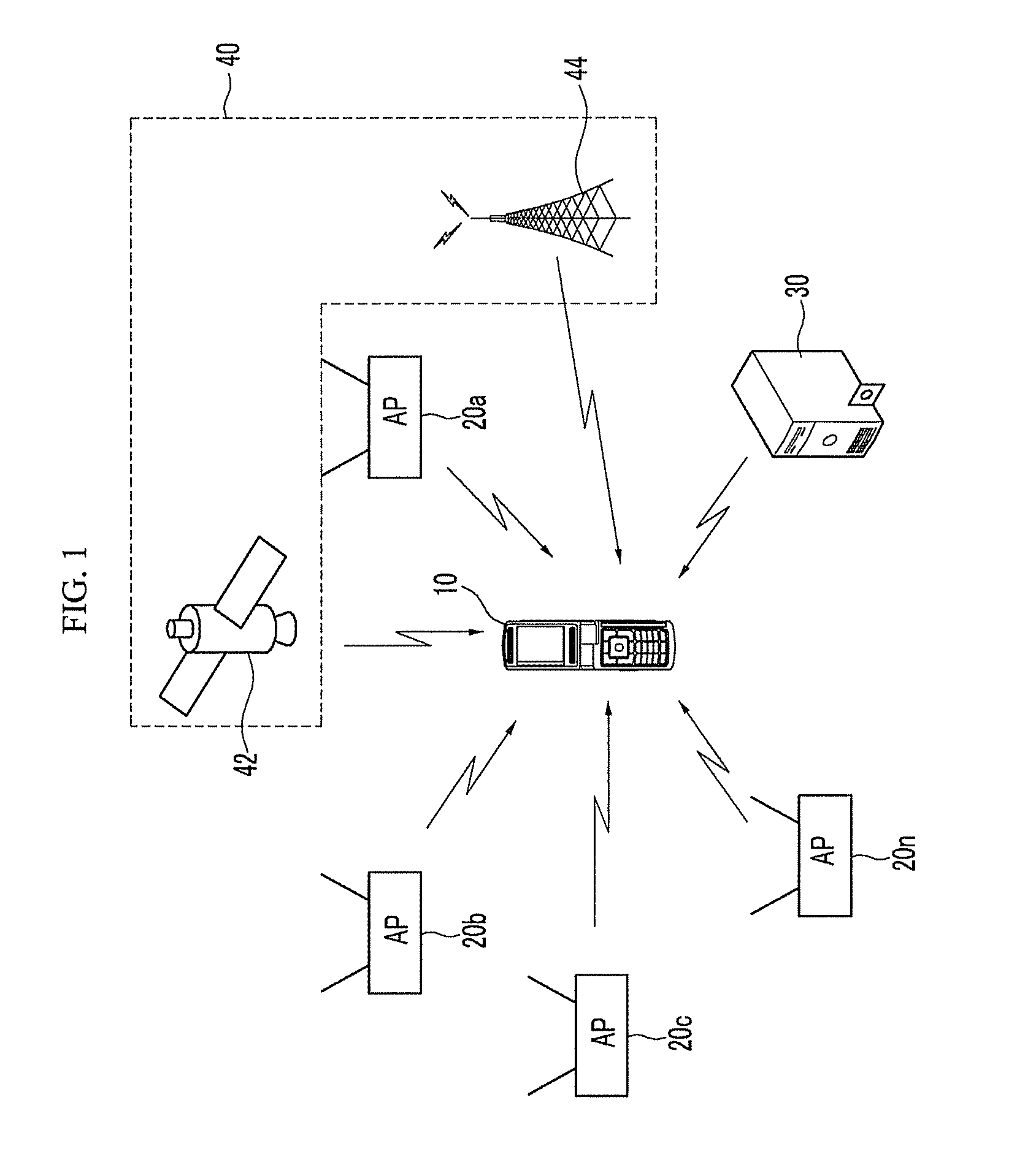
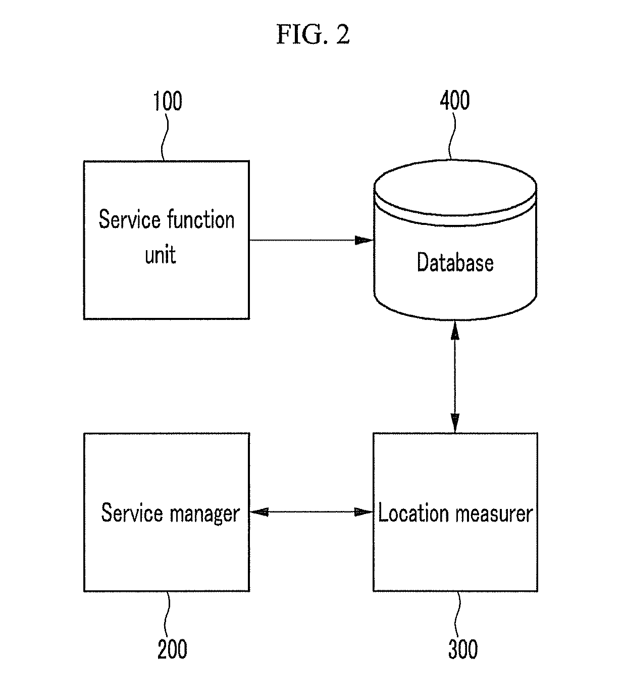
A terminal location measuring device includes a database for storing registration information of a plurality of access points (AP's) forming a first infrastructure system for wireless LAN-based indoor location determination. The terminal location measuring device sets a search range of a database by using location information of the terminal acquired through a second infrastructure system that is different from the first infrastructure system, an identifier of at least one of a plurality of AP's, and a signal measurement value. The terminal location measuring device extracts registration information of an AP having the same identifier as at least one AP within the search range of the database, and measures a location of the terminal by using registration information of the AP.

Description

CROSS-REFERENCE TO RELATED APPLICATION[0001]This application claims priority to and the benefit of Korean Patent Application No. 10-2009-0087712 filed in the Korean Intellectual Property Office on Sep. 16, 2009, the entire contents of which are incorporated herein by reference.BACKGROUND OF THE INVENTION[0002](a) Field of the Invention[0003]The present invention relates to a method and device for measuring a location of a terminal.[0004](b) Description of the Related Art[0005]There are various location determination technologies using a radio infrastructure depending on infrastructure types and service ranges.[0006]A global navigation satellite system (GNSS) is a system for determining a location of a user by using a signal of a satellite in orbit of the earth. The GNSS provides high location accuracy having an error of location information within 10 m and availability in the case of level ground or suburbs acquiring a direct line of sight of a satellite and a receiver. On the contr...

Claims


Application Information

Patent Timeline
IPC IPC(8): H04L12/28
CPCH04L67/18H04W64/00H04L67/52G01S5/0252G01S5/01G06F16/29
Inventor KIM, BYUNG DOOCHO, YOUNGSUYUN, SUNG JOJI, MYUNG IN
Owner ELECTRONICS & TELECOMM RES INST
Learn More