Portion capsule and use of a portion capsule

a technology of portion capsules and capsules, which is applied in the field ofportion capsules, can solve the problems of filter elements that cannot be wiped out, modern coffee extraction machines operating at relatively high pressure, and the possibility of filter elements being washed upwards or floating upwards, so as to maximize the swirl formation, and improve the quality of the beverag

Inactive Publication Date: 2011-03-17
K FEE SYST
View PDF15 Cites 131 Cited by
  • Summary
  • Abstract
  • Description
  • Claims
  • Application Information

AI Technical Summary

Benefits of technology

[0006]The portion capsule according to the invention has the advantage over the portion capsule according to the prior art that the filter element is fixedly connected to the base element. Firstly, therefore, the portion capsule is considerably less susceptible to being shaken and to the action of external force, for example during storage or transportation, and secondly, extraction under considerably higher pressures is made possible. The risk of the beverage which is produced from the portion capsule being contaminated with beverage raw material is reduced, and an improvement is therefore obtained in the quality of the beverage produced. Here, the fastening means is arranged in particular on a side which is situated opposite the membrane along a direction perpendicular to a main plane of extent of the membrane. Said side of the base element is also referred to hereinafter as the bottom region. That surface of the filter element which faces towards the beverage raw material and through which in particular filter openings extend is referred to hereinafter as the filter surface.
[0040]According to a further subject matter or a preferred refinement of the present invention, it is provided that the filter element has a multiplicity of filter openings, with the filter openings having, at least on a side facing towards the membrane, a mean diameter which amounts to between 40 and 400 percent, preferably to between 55 and 135 percent and particularly preferably to substantially 80 percent of the spacing between the filter element and the bottom region perpendicular to a main plane of extent of the membrane. It has been found that such a percentage ratio between the diameters of the filter openings and the mean spacing between the filter element, in particular the filter surface, and the bottom region maximize the swirl formation in the second region, as a result of which a considerable increase in quality of the beverage to be produced is obtained, as already discussed in detail above.

Problems solved by technology

A disadvantage of said portion capsule is that the filter element is not fixedly connected to the base element, and a relative movement between the filter element and the base element is therefore possible.
Therefore, in particular during the transportation and storage of the portion capsules, the possibility of the filter element slipping out of place cannot be ruled out.
Furthermore, modern coffee extraction machines operate at relatively high pressures, as a result of which there is the risk of the filter element in the portion capsule being washed upwards or floating upwards during the injection of the extraction liquid into the first region.
During production of the beverage, said beverage raw material is subsequently conducted into the beverage receptacle, thereby impairing the quality of the beverage.
In the case of coffee powder, for example, being used as a beverage raw material, this results in an undesired bitter taste of the coffee beverage, and residues of the raw coffee material can be found in the beverage receptacle.

Method used


Image

  • Portion capsule and use of a portion capsule
  • Portion capsule and use of a portion capsule
  • Portion capsule and use of a portion capsule

Examples


seventh embodiment

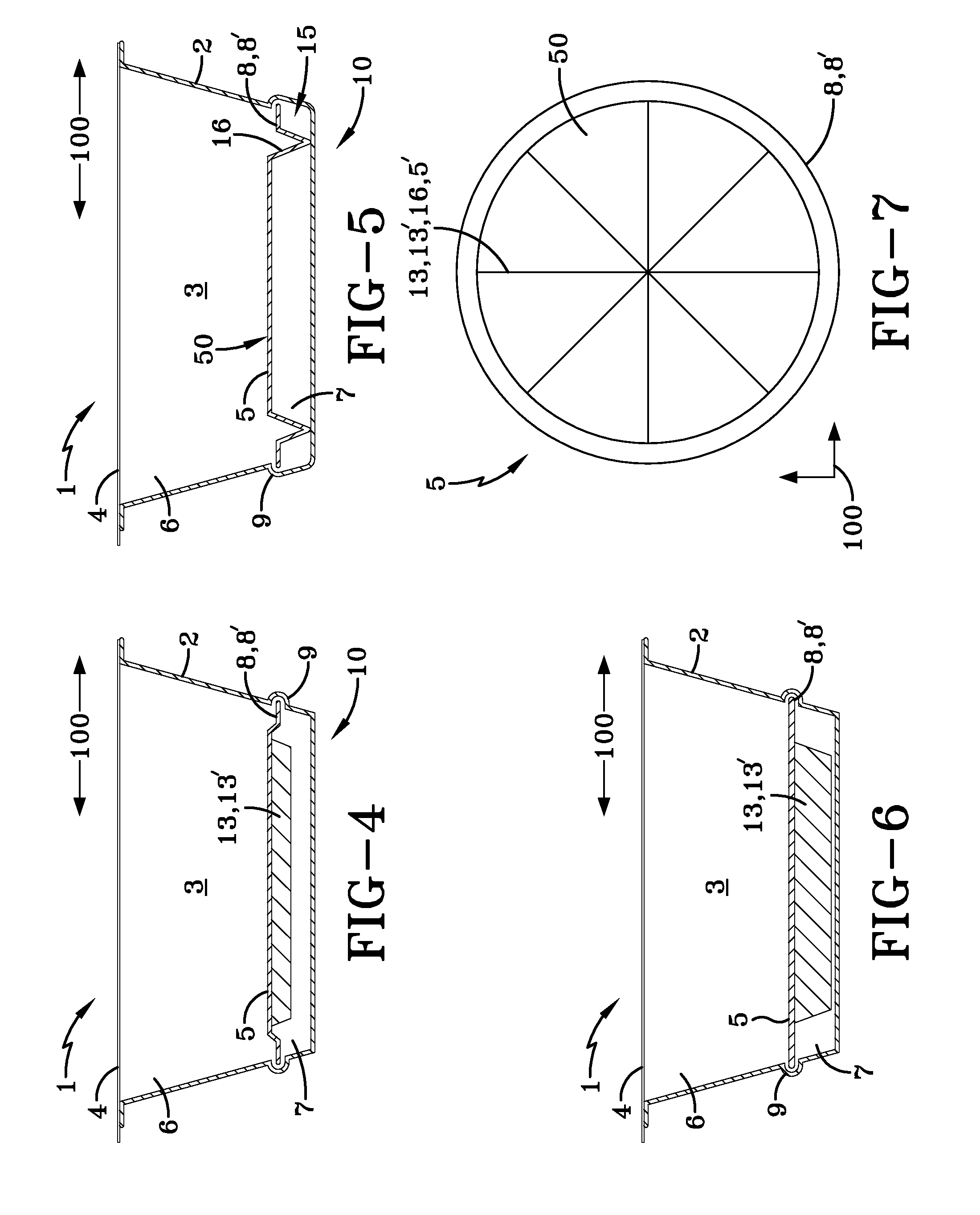
[0069]FIG. 8 shows a schematic side-on sectional view of a portion capsule 1 according to the present invention. It can be seen in said perspective that the reinforcement struts 13′ are curved relative to the main plane of extent 100, which is parallel to the membrane 4, such that the end regions of the reinforcement struts 13′ are supported on the bottom region 10. The reinforcement struts 13′ therefore simultaneously comprise support structures 16 which are provided for spacing the filter element 5 apart from the bottom region 10. On account of the curved design of the reinforcement struts 13′, the reinforcement struts 13′ comprise a particularly stable arch structure 5′ in the form of an ellipsoidal shell or spherical shell.

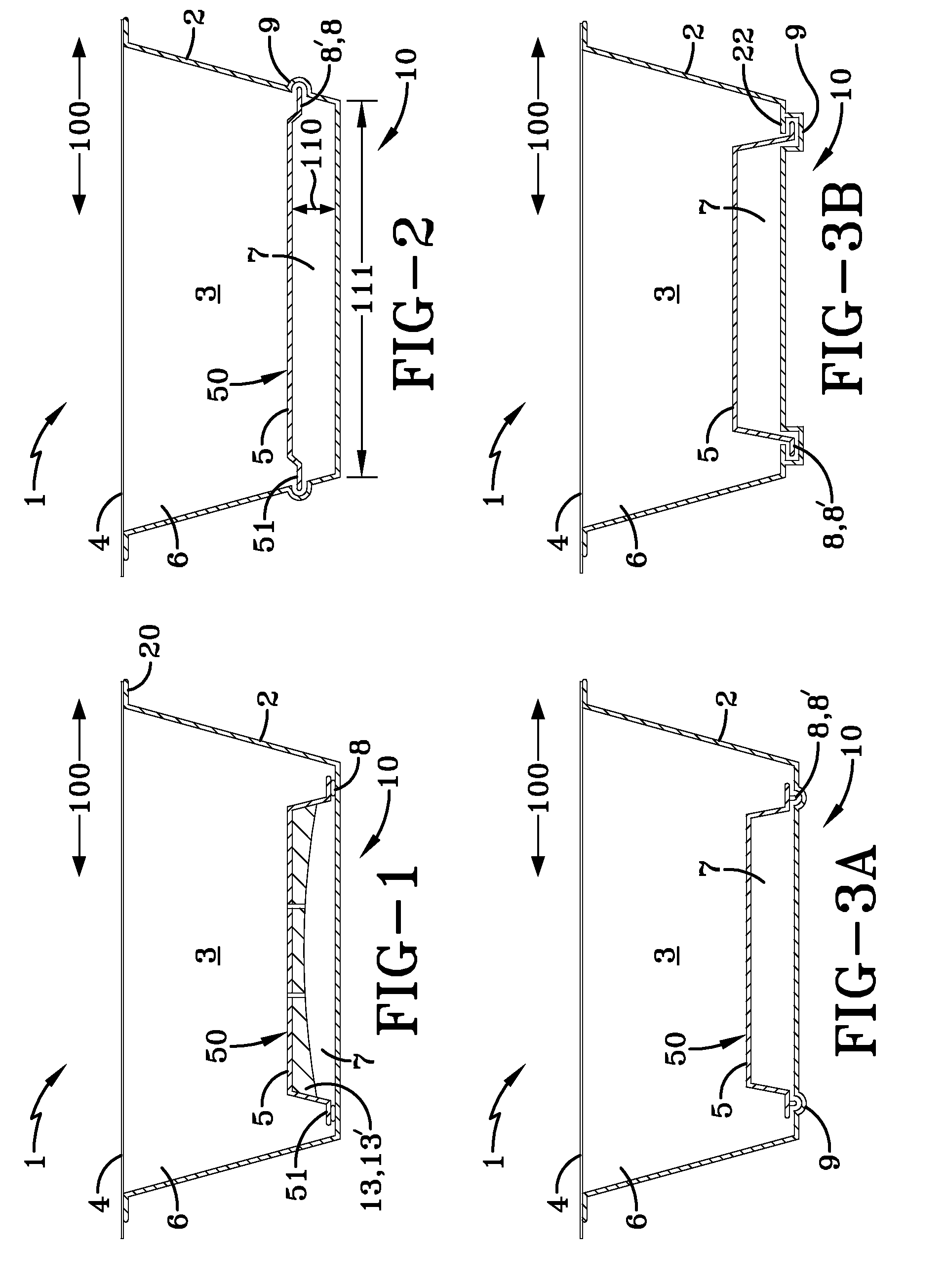
[0070]FIG. 9 illustrates a schematic, side-on sectional view of a portion capsule 1 according to an eighth embodiment of the present invention, with the eighth embodiment being substantially identical to the third embodiment illustrated in FIG. 3a, with the fi...

eighth embodiment

[0071]FIG. 10 illustrates a schematic plan view of a filter element 5 of a portion capsule 1 according to the present invention, with the filter element 5 being illustrated in particular from the underside, that is to say as viewed from the bottom region 10. It can be seen from FIG. 10 that the columns 16′ are arranged so as to be distributed non-uniformly, so as not to adversely affect the swirl formation, or so as to promote the swirl formation, in the beverage extract in the second region 7 during the extraction.

[0072]FIG. 11 illustrates a schematic plan view of a filter element 5 of a portion capsule 1 according to a ninth embodiment of the present invention, with the ninth embodiment being substantially identical to the eighth embodiment illustrated in FIG. 10, with the columns 16′ being arranged in a uniform annular and crossed structure.

[0073]FIG. 12 illustrates a schematic, side-on sectional view of a portion capsule 1 according to a tenth embodiment of the present invention...


PUM


Abstract

Proposed is a portion capsule for producing a beverage, having a substantially frustoconical or cylindrical base element which has a cavity, and having a membrane which closes off the cavity, with a filter element being arranged within the cavity, which filter element divides the cavity into a first region for holding beverage raw material and a second region for holding a beverage extract, with the filter element being fastened to the base element by at least one fastening means which is arranged substantially in the region of a side, which is situated opposite the membrane, of the base element.

Description

BACKGROUND[0001]The present invention relates to a portion capsule for producing a beverage, having a substantially frustoconical or cylindrical base element which has a cavity, and having a membrane which closes off the cavity, with a filter element being arranged within the cavity, which filter element divides the cavity into a first region for holding beverage raw material and a second region for holding a beverage extract.[0002]Such portion capsules are generally known. For example, the document FR 2 556 323 A1 discloses a portion capsule which has a frustoconical or cylindrical base element and which is used for producing a beverage, with the first region of the cavity within the portion capsule being filled with beverage raw material, in particular coffee powder. To produce a coffee beverage, the portion capsule is arranged in a brewing chamber in which the membrane is perforated and an extraction liquid, in particular hot water, is introduced into the first region. The extrac...

Claims


Application Information

Patent Timeline
Patent Type & Authority Applications(United States)
IPC IPC(8): B65B29/02A23L2/52
CPCB65D85/8043B65D85/8061
Inventor MANN, TORSTEN
Owner K FEE SYST
Why Eureka
Try Eureka