Process and plant for producing methanol

a technology of methanol and process, applied in the field of methanol production, can solve the problems of reducing the amount of carbon oxides converted in the water-cooled reactor, and reducing the maximum methanol yield to be achieved, and achieve the effect of high methanol yield

Active Publication Date: 2011-03-17
LURGI
View PDF6 Cites 38 Cited by
  • Summary
  • Abstract
  • Description
  • Claims
  • Application Information

AI Technical Summary

Benefits of technology

[0007]In accordance with a development of the invention, the amount of the partial stream guided past the first reactor lies in the range from 0 to 20 vol-%, preferably 5 to 15 vol-%, and in particular is about 10 vol-% of the recirculated synthesis gas. In this way, the desired inlet temperature of the gas mixture at the second reactor can be achieved.
[0008]To counter the passivation of the ageing catalyst in the first reactor, the temperature in the reactor is raised deliberately by increasing the vapor pressure. As a result, the outlet temperature of this reactor is also increased. In accordance with a particularly preferred aspect it is therefore provided that the size of the partial stream guided past the first reactor is controlled in dependence on the temperature of the gas mixture at the outlet of the first reactor. As a result, an optimum adaptation of the inlet temperature of the second reactor to the condition of the first reactor is achieved, so that a maximum methanol yield becomes possible.
[0010]To achieve a suitable inlet temperature for the first reactor, the synthesis gas is introduced into the second reactor as coolant and thereby preheated. Additional heating means can be avoided thereby.

Problems solved by technology

However, the amount of carbon oxides converted in the water-cooled reactor decreases with the ageing of the catalyst, which leads to the fact that a large part of the total conversion of methanol takes place in the gas-cooled reactor.
An increase in temperature, however, causes a shift of the reaction equilibrium towards the educts in the gas cooled reactor, which means a reduction of the maximum methanol yield to be achieved.

Method used


Image

  • Process and plant for producing methanol
  • Process and plant for producing methanol

Examples


example

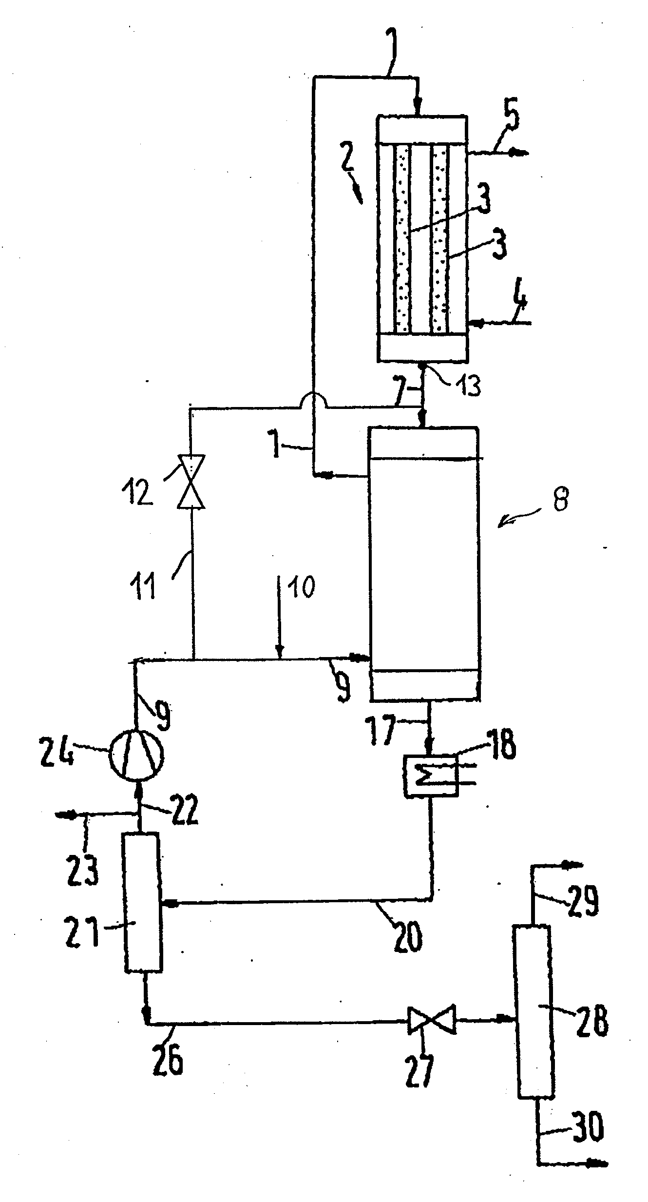
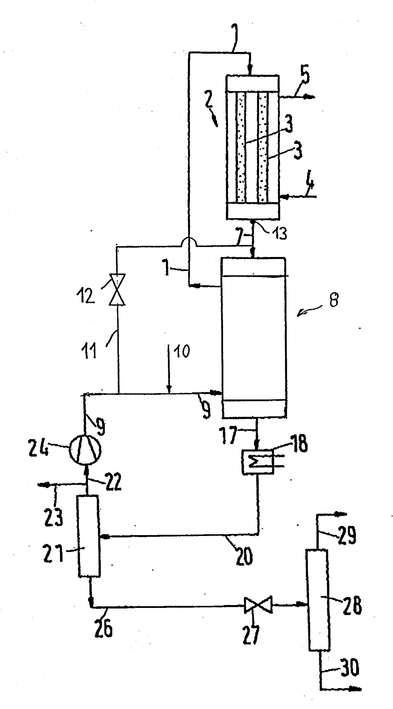
[0027]Via conduit 9, a mixture of recirculated synthesis gas and fresh synthesis gas is supplied to the second reactor 8 as cooling gas. The recirculated synthesis gas has a temperature of about 60° C., whereas the fresh synthesis gas has a temperature of about 160° C. The mixing ratio initially is chosen such that a mixing temperature of about 120° C. is obtained. When the gas outlet temperature of the first reactor 2 is increased, the mixing temperature of the cooling gas at the lower inlet of the second reactor 8 can for instance also be decreased to 90° C., in order to compensate the higher temperature of the synthesis gas. Upon traversing the gas-cooled reactor 8 as coolant, the temperature of the synthesis gas which is introduced into the water-cooled first reactor 2 via conduit 1 with a pressure of about 8 MPa (80 bar) is increased to about 230 to 240° C., in any case greater than 220° C. Due to the exothermal reaction and simultaneous cooling in the first reactor 2, the firs...


PUM

PropertyMeasurementUnit
temperatureaaaaaaaaaa
ignition temperatureaaaaaaaaaa
temperatureaaaaaaaaaa

Abstract

In the production of methanol from a synthesis gas containing hydrogen and carbon oxides, the synthesis gas is passed through a first, preferably water-cooled reactor, in which a part of the carbon oxides is catalytically converted to methanol. The obtained mixture containing synthesis gas and methanol vapor is supplied to a second, preferably gas-cooled reactor, in which a further part of the carbon oxides is converted to methanol. Subsequently, methanol is separated from the synthesis gas, and the synthesis gas is recirculated to the first reactor. To achieve a maximum methanol yield even with an aged catalyst, a partial stream of the synthesis gas is guided past the first reactor and introduced directly into the second reactor.

Description

CROSS-REFERENCE TO RELATED APPLICATIONS[0001]This application is a national stage application under 35 U.S.C. 371 of International Patent Application Serial No. PCT / EP2008 / 006759, entitled “Verfahren and Anlage zur Herstellung von Methanol,” filed Aug. 18, 2008, which claims priority from German Patent Application No. 10 2007 040 707.8, filed Aug. 29, 2007.FIELD OF THE INVENTION[0002]This invention relates to the production of methanol from a synthesis gas containing hydrogen and carbon oxides, wherein the synthesis gas is passed through a first, preferably water-cooled reactor, in which a part of the carbon oxides is catalytically converted to methanol, wherein the obtained mixture containing synthesis gas and methanol vapor is supplied to a second, preferably gas-cooled reactor, in which a further part of the carbon oxides is catalytically converted to methanol, wherein methanol is separated from the synthesis gas and wherein synthesis gas is recirculated to the first reactor.BACK...

Claims


Application Information

Patent Timeline
Patent Type & Authority Applications(United States)
IPC IPC(8): C07C29/00B01J19/00
CPCB01J8/0488B01J8/0496B01J8/067B01J2208/00212C07C29/1516B01J2208/0053C07C31/04
Inventor MUELLER, DIERKBORMANN, ANDREAS
Owner LURGI
Why Eureka
Try Eureka