Combined heat exchanger unit with electric heat pump and absorption heat pump

A technology of absorption heat pumps and heat exchange units, which is applied in the direction of adsorption machines, heat pumps, refrigerators, etc., can solve the problems of high operating costs, heat exchange process losses, and low grades, so as to reduce irreversible losses, reduce operating costs, The effect of raising the outlet temperature

Pending Publication Date: 2018-09-28
NORTH CHINA ELECTRIC POWER UNIV (BAODING)
View PDF16 Cites 8 Cited by
  • Summary
  • Abstract
  • Description
  • Claims
  • Application Information

AI Technical Summary

Problems solved by technology

[0002] Natural gas, coal and petroleum are widely used in various industrial occasions. There are a lot of waste heat and waste heat in different technological processes, especially in the petrochemical industry. These waste heat and waste heat are usually of low grade. The heat pump technology is difficult to recycle, which leads to low energy efficiency of the system
[0003] The heat pump technology is more commonly used in the current industrial waste heat recovery technology. If the absorption heat pump technology is used, no matter it is a first-class absorption heat pump or a second-class absorption heat pump, due to the limitation of the absorption heat pump process or the working medium of lithium bromide, it is used. There are restrictions on the outlet temperature of the heating medium; if electric heat pump technology is used, the high power consumption of the electric heat pump leads to high operating costs
[0004] The current absorption heat pumps and electric heat pumps are used in series or parallel connection of external waterways. Since each heat exchanger of the heat pump has a heat transfer end difference, this leads to irreversible losses during the heat transfer process.

Method used


Image

  • Combined heat exchanger unit with electric heat pump and absorption heat pump
  • Combined heat exchanger unit with electric heat pump and absorption heat pump
  • Combined heat exchanger unit with electric heat pump and absorption heat pump

Examples


Embodiment Construction

[0032] In order to make the objectives, technical solutions and advantages of the present invention clearer, the technical solutions in the embodiments of the present invention will be described in more detail below in conjunction with the drawings in the embodiments of the present invention. In the drawings, the same or similar reference numerals denote the same or similar elements or elements having the same or similar functions throughout. The described embodiments are some, but not all, embodiments of the invention. The embodiments described below by referring to the figures are exemplary and are intended to explain the present invention and should not be construed as limiting the present invention. Based on the embodiments of the present invention, all other embodiments obtained by persons of ordinary skill in the art without creative efforts fall within the protection scope of the present invention.

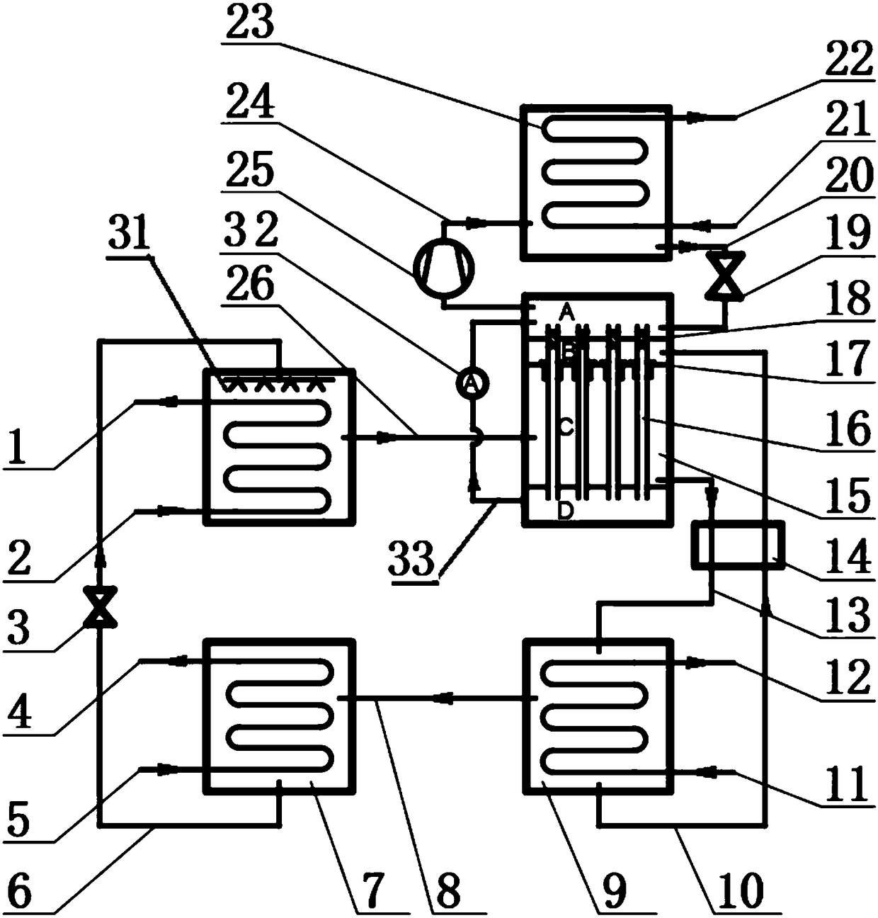
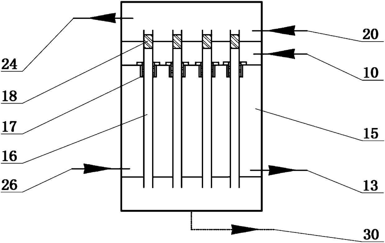
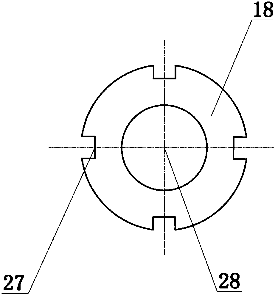
[0033] Such as Figure 1-6 As shown, a heat exchange unit combined w...


PUM


Abstract

The invention provides a combined heat exchanger unit with an electric heat pump and an absorption heat pump. The heat exchanger unit comprises an electric heat pump condenser, a bilateral phase change heat exchanger, an absorption heat pump generator, an absorption heat pump condenser, an absorption heat pump evaporator and a pipeline and can be widely applied to various low-grade waste heat recovery occasions. The heat exchanger unit adopts the combined structure of the absorber of the absorption heat pump and an electric heat pump evaporator and can greatly raise the outlet temperature of aheated medium. Compared with the technology only adopting the absorption heat pump, the heat exchanger unit releases the maximum outlet temperature limit caused by the heat pump process and a workingmedium. Compared with the technology only adopting the electric heat pump, the heat exchanger unit greatly reduces powder consumption and significantly reduces the operating cost of equipment. The novel unit has a certain application prospect in the field of energy conservation and environmental protection.

Description

technical field [0001] The invention relates to the technical field of thermal energy utilization, in particular to a heat exchange unit combined with an electric heat pump and an absorption heat pump. Background technique [0002] Natural gas, coal and petroleum are widely used in various industrial occasions. There are a lot of waste heat and waste heat in different technological processes, especially in the petrochemical industry. These waste heat and waste heat are usually of low grade. The existing heat pump technology is difficult to recycle, which leads to low energy efficiency of the system. [0003] The heat pump technology is more commonly used in the current industrial waste heat recovery technology. If the absorption heat pump technology is used, no matter it is a first-class absorption heat pump or a second-class absorption heat pump, due to the limitation of the absorption heat pump process or the working medium of lithium bromide, it is used. There are restri...

Claims


Application Information

Patent Timeline
Patent Type & Authority Applications(China)
IPC IPC(8): F25B15/06F25B30/06
CPCF25B15/06F25B30/06Y02B30/62Y02A30/27
Inventor 孙健戈志华杜小泽杨勇平
Owner NORTH CHINA ELECTRIC POWER UNIV (BAODING)
Why Eureka
Try Eureka