Multistage absorption refrigerating/heat pump unit

A technology of absorption refrigeration and heat pump units, which is applied in the direction of refrigerators, adsorption machines, refrigeration and liquefaction, etc., and can solve the problems of reducing the heat exchange temperature difference between the refrigerant solution and cooling water, reducing irreversible losses, and the appearance of the unit is huge. , to achieve the effect of compact structure, reduced irreversible loss and convenient maintenance

Active Publication Date: 2010-02-17
TSINGHUA UNIV +1
View PDF2 Cites 16 Cited by
  • Summary
  • Abstract
  • Description
  • Claims
  • Application Information

AI Technical Summary

Problems solved by technology

Patent No. 01133610.2 proposes that the multi-stage absorption refrigeration device adopts conventional absorbers to be connected in series. Although the heat exchange temperature difference between the refrigerant solution and the cooling water is reduced to a certain extent, and the irreversible loss is reduced, there are still problems with the appearance of the unit being too large, Disadvantages of inconvenient maintenance

Method used


Image

  • Multistage absorption refrigerating/heat pump unit
  • Multistage absorption refrigerating/heat pump unit
  • Multistage absorption refrigerating/heat pump unit

Examples


Embodiment 1

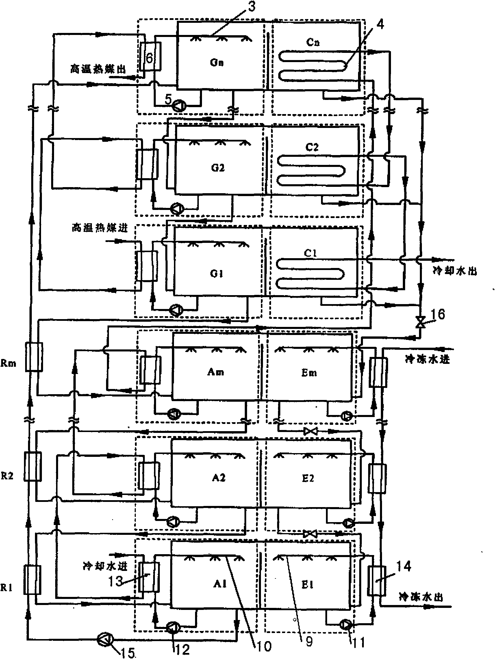
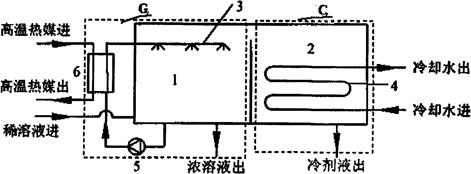
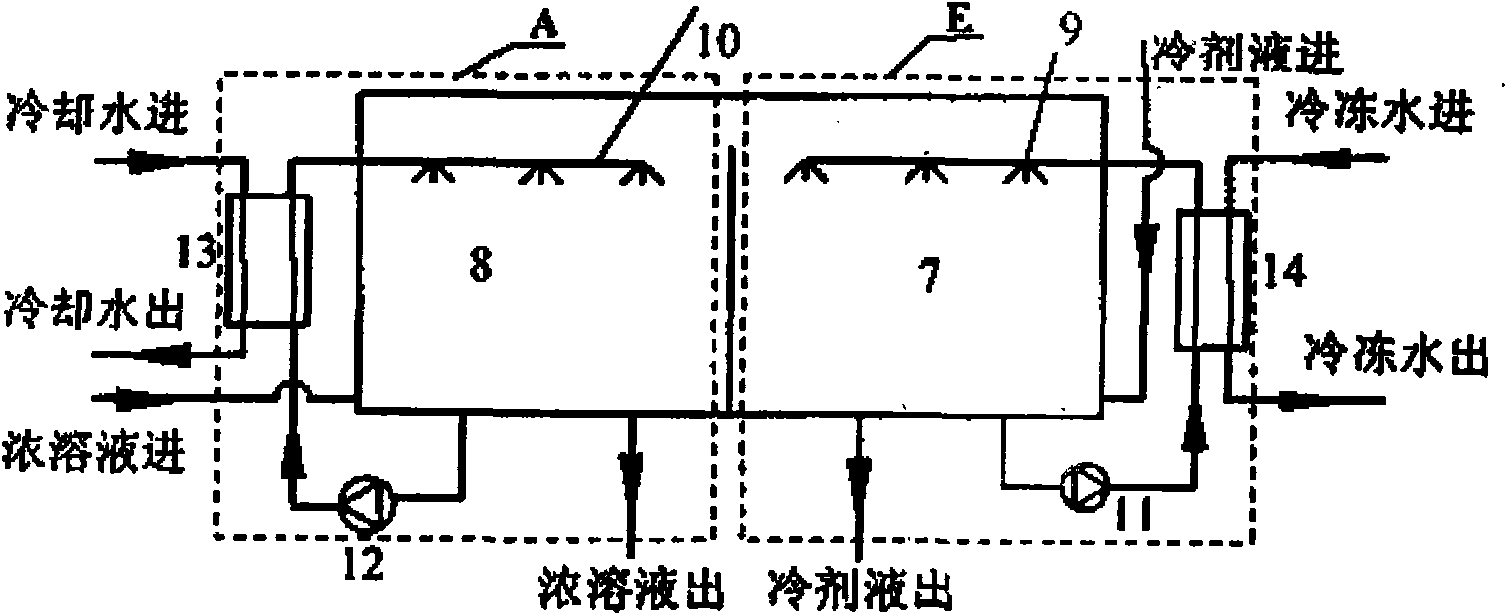
[0019] Embodiment 1: as figure 1 , 2 、 As shown in 3, the multi-stage absorption refrigeration / heat pump unit consists of an adiabatic generator G 1 ~G n , Conventional condenser C 1 ~C n , Adiabatic absorber A 1 ~A m , evaporator E 1 ~E m , solution heat exchanger R 1 ~ Rm, solution pump, 2m throttling valves are connected through pipelines according to the heat exchange process of working fluid. The high-temperature heat medium passes through the adiabatic generator G in sequence 1 , adiabatic generator G 2 , ..., adiabatic generator G n , heating refrigerant solution; from adiabatic absorber A 1 dilute solution, through the solution heat exchanger R 1 , solution heat exchanger R 2 , ..., the solution heat exchanger Rm, after being heated by the high-temperature and high-concentration refrigerant solution, it enters the adiabatic generator G in sequence n , adiabatic generator G (n-1) , ..., adiabatic generator G 1 Carry out stepwise variable temperature hea...

Embodiment 2

[0021] Embodiment 2: as Figure 4 As shown, the absorber and the cooling water of the condenser are connected in parallel. The absorption unit consists of an adiabatic generator G 1 , adiabatic generator G 2 , ..., adiabatic generator G n , Conventional condenser C 1 , Conventional condenser C 2 , ..., conventional condenser C n , Adiabatic absorber A 1 , Adiabatic absorber A 2 , ..., adiabatic absorber A m , evaporator E 1 , evaporator E 2 , ..., evaporator E m , solution heat exchanger R 1 , solution heat exchanger R 2 , ..., a solution heat exchanger Rm, a solution pump, and 2m throttling valves 16 are formed by connecting pipelines. The high-temperature heat medium enters the adiabatic generator G sequentially 1 , adiabatic generator G 2 , ..., adiabatic generator G n , heating refrigerant solution; from adiabatic absorber A 1 Refrigerant dilute solution, through the solution heat exchanger R 1 , solution heat exchanger R 2 , ..., the solution heat excha...

Embodiment 3

[0023] Embodiment 3: as Figure 5 As shown, the high-temperature heat medium from the generator passes through the heat exchanger to exchange heat with the cooling water, then enters the evaporator after lowering the temperature, and further releases heat, which can effectively realize the cascade utilization of energy, improve energy utilization rate, and cool water two ways. The absorption unit consists of an adiabatic generator G 1 , adiabatic generator G 2 , ..., adiabatic generator G n , Conventional condenser C 1 , Conventional condenser C 2 , ..., conventional condenser C n , Adiabatic absorber A 1 , Adiabatic absorber A 2 , ..., adiabatic absorber A m , evaporator E 1 , evaporator E 2 , ..., evaporator E m , solution heat exchanger R 1 , solution heat exchanger R 2 , ..., the solution heat exchanger Rm, the third solution pump 15, the water-to-water heat exchanger 17, and 2m throttling valves 16 are connected by connecting pipelines. and Figure 4 The di...


PUM


Abstract

The invention discloses a multistage absorption refrigerating/heat pump unit, consisting of two or more single-stage generating-condensation units and two or more single-stage absorption-evaporation units, a solution heat exchanger, a throttling device, a meter, a valve and a connection pipeline. The single-stage generating-condensation unit consists of a heat insulating generator and a regular condenser, the single-stage absorption-evaporation unit consists of a heat insulating absorber and an evaporator, the single-stage generating-condensation units are serially connected, and the single-stage absorption-evaporation units are serially connected. A refrigerating working medium diluted solution is gradually heated and flash-evaporated in each heat insulating generator, the flash-evaporated concentrated solution is gradually cooled to absorb refrigerant steam in each heat insulating absorber to become the diluted solution, and refrigerant solution is gradually throttled, decompressed and evaporated in each evaporator. Through gradually changing temperature and exchanging heat, reducing the temperature difference of exchanging heat and lowering irreversible loss in the process of exchanging heat, the performance of the unit is improved, and the unit is convenient to be inspected and fixed.

Description

technical field [0001] The invention belongs to the field of absorption heat exchange systems, and in particular relates to a multistage absorption refrigeration / heat pump unit using binary solution as a working medium in a heat exchange process; it can be used for refrigeration and heating, and can also be used for industrial waste heat recovery. Background technique [0002] In order to solve the problem of difficult peak regulation in winter and summer of the city's power grid, an absorption refrigeration / heat pump unit is introduced to alleviate the peak regulation pressure of the power grid to a certain extent. In enterprises with a large amount of industrial waste heat, absorption units can be used to recover a large amount of industrial waste heat to realize centralized heating or cooling for nearby areas. This is of great significance for improving energy utilization, alleviating energy shortage and protecting the ecological environment. [0003] For conventional ab...

Claims


Application Information

Patent Timeline
Patent Type & Authority Applications(China)
IPC IPC(8): F25B15/00F25B15/06
CPCY02B30/62Y02A30/27
Inventor 付林孙方田张世钢江亿罗勇肖常磊胡鹏
Owner TSINGHUA UNIV
Why Eureka
Try Eureka