Bone joint suture button and grommet and kit using same

a bone joint and button technology, applied in the field of improved bone joint suture grommets, bone joint suture buttons and bone joint suture kits using same, can solve the problems of large bone anchors used to secure sutures, irritate soft tissue, etc., and achieve the effect of reducing the wear of sutures and the bone, simple and easy installation

Inactive Publication Date: 2011-03-17
MWI VETERINARY SUPPLY
View PDF5 Cites 32 Cited by
  • Summary
  • Abstract
  • Description
  • Claims
  • Application Information

AI Technical Summary

Benefits of technology

It is a further object of this invention to provide such an improved bone joint button and bone joint grommet which reduce wear on the sutures and the bone.
It is a further object of this invention to provide such an improved bone joint which are simple and easy to install and do not present sharp, prominent edges to soft tissue.
It is a further object of this invention to provide such an improved bone joint button which is chamfered or tapered where it engages the hole in the bone for a self-centering and stabilizing the button in the hole.
In a preferred embodiment each suture passage may be chamfered along at least a part of its inner edge to provide smooth surfaces for bearing on the suture. Each chamfered edge may be radiused. Each body may be round. The lower edge of the body may be chamfered for a self-centering and stabilizing the body in a hole in the bone. The edge of the top surface of the body may be chamfered to avoid irritation of soft tissue. This invention also features a bone joint suture grommet including a shaft having a suture passage therethrough, a head having an opening therethrough to the suture passage and drive surface configured to receive a drive tool to set the grommet in a hole in a bone joint, the opening having its inner edge chamfered to provide a smooth continuous surface for bearing against the suture.

Problems solved by technology

Over time through cycles of joint movement two serious problems arise.
Further, bone anchors used to secure the sutures may be large and irritate the soft tissue.

Method used


Image

  • Bone joint suture button and grommet and kit using same
  • Bone joint suture button and grommet and kit using same
  • Bone joint suture button and grommet and kit using same

Examples


Embodiment Construction

Aside from the preferred embodiment or embodiments disclosed below, this invention is capable of other embodiments and of being practiced or being carried out in various ways. Thus, it is to be understood that the invention is not limited in its application to the details of construction and the arrangements of components set forth in the following description or illustrated in the drawings. If only one embodiment is described herein, the claims hereof are not to be limited to that embodiment. Moreover, the claims hereof are not to be read restrictively unless there is clear and convincing evidence manifesting a certain exclusion, restriction, or disclaimer.

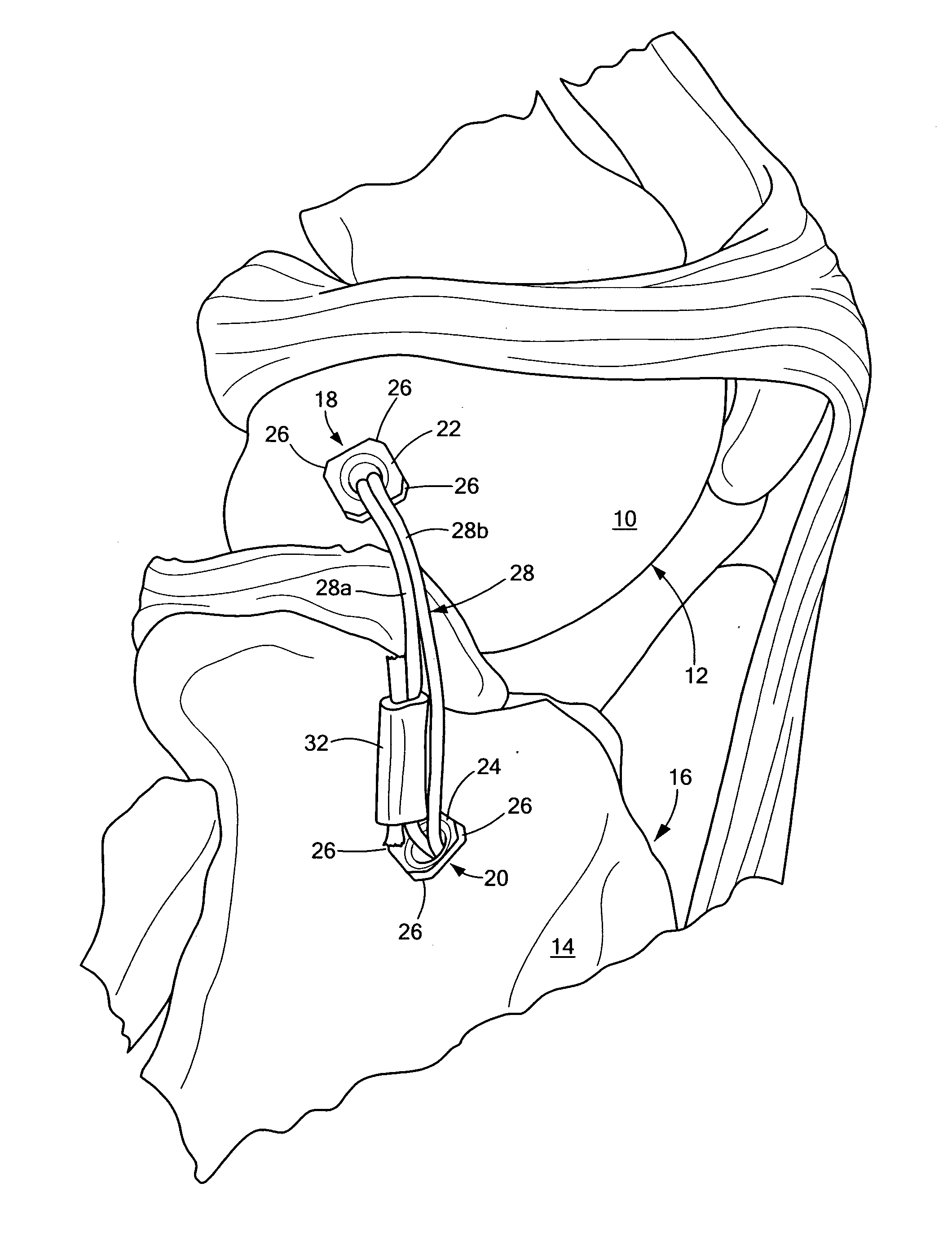
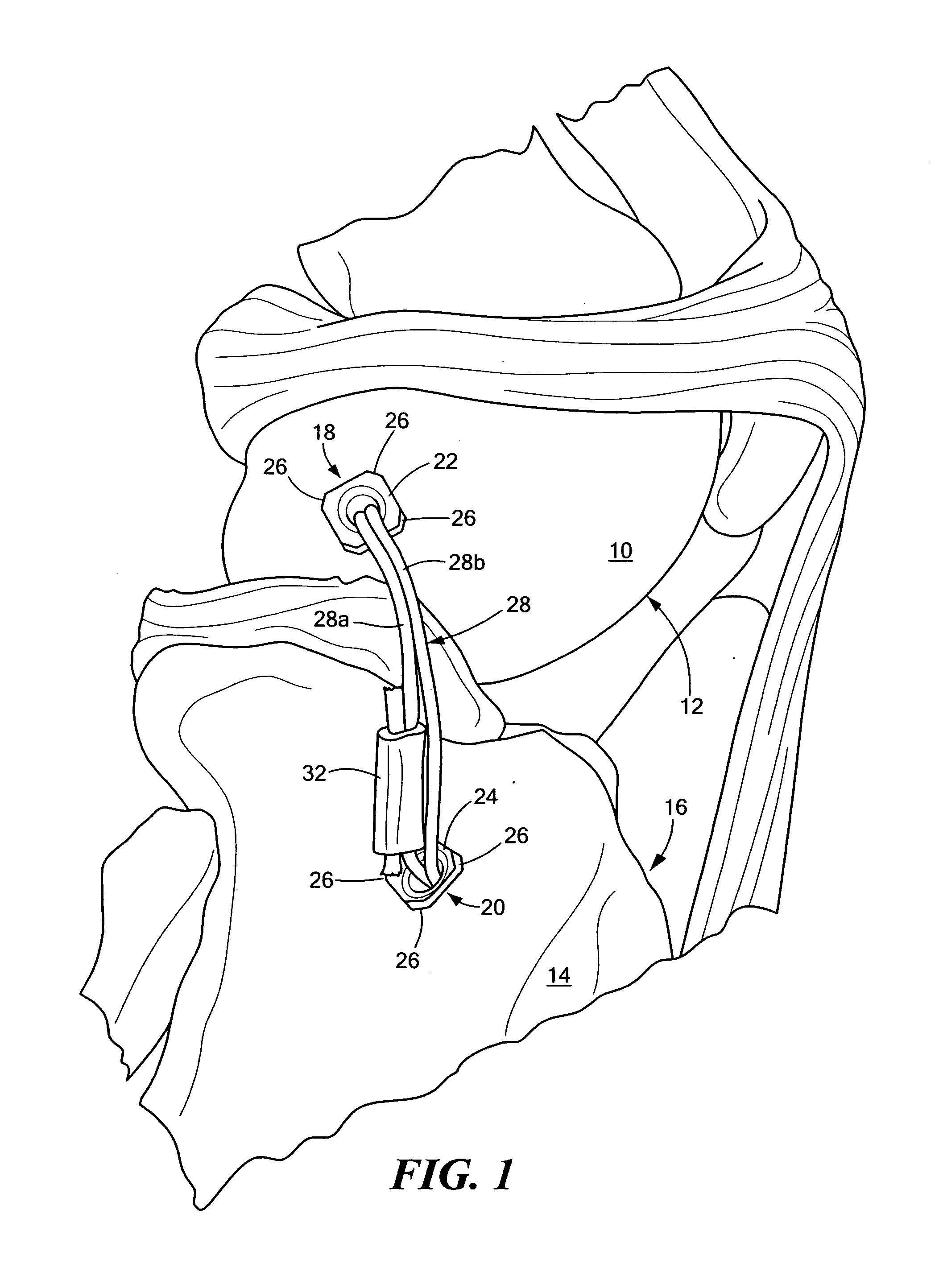
There is shown in FIG. 1 the lateral side 10 of a femur 12 and the lateral side 14 of a tibia 16 which have been joined together using one embodiment of the suture buttons, grommets, and kit according to this invention. A hole is drilled through femur 12 from the lateral side 10 and tibia 16 through the lateral side 14. Suture gr...


PUM


Abstract

An improved bone joint suture button including a body having a channel extending across at least a portion of the top surface of the body, a pair of suture passages extending from the channel inclined, inwardly to the bottom of the body, and a bridge portion recessed from the body top surface between the suture passages and having a curved upper surface for providing a smooth surface for bearing against the suture; and an improved bone joint suture grommet including a pair of grommets to be inserted into holes drilled in a bone, each grommet including a hollow shaft and a head portion having a top with a chamfered channel in communication with the interior of the hollow shaft, a pair of buttons each including a chamfered side wall, a top with a chamfered channel therein, and a pair of inwardly angled suture passages extending from the channel through the button and separated by a chamfered portion, and at least one suture strand looped through the pair of inwardly angled suture passages of one button over the chamfered portion and secured to a needle.

Description

FIELD OF THE INVENTIONThis invention relates to an improved bone joint suture grommet, bone joint suture button and a bone joint suture kit using same.BACKGROUND OF THE INVENTIONLateral suture techniques are used to repair a wide variety of bone joint problems in humans and animals such as dogs. In one of many applications a knee joint is repaired by drilling a hole from the lateral side of the femur to the medial side and another hole is drilled from the lateral side of the tibia to the medial side. A suture is inserted through both holes and then secured to stabilize the knee joint. Over time through cycles of joint movement two serious problems arise. The suture strands saw through the bone and / or the bone wears away and weakens the suture strands. Further, bone anchors used to secure the sutures may be large and irritate the soft tissue.SUMMARY OF THE INVENTIONIt is therefore an object of this invention to provide an improved bone joint button, bone joint grommet, and a bone joi...

Claims


Application Information

Patent Timeline
Patent Type & Authority Applications(United States)
IPC IPC(8): A61B17/04
CPCA61B17/0401A61B17/0469A61B17/0487A61B2017/0404A61F2002/0882A61F2/0811A61F2002/0841A61F2002/0852A61B2017/06052
Inventor WOTTON, III, HAROLD M.
Owner MWI VETERINARY SUPPLY
Why Eureka
Try Eureka