Multi-axis serially redundant, single channel, multi-path fly-by-wire flight control system

a flight control system and serial redundant technology, applied in process and machine control, instruments, navigation instruments, etc., can solve problems such as significant increase in aircraft weight, complex laws, and possible basic mechanical failure mode contingency in such systems

Active Publication Date: 2011-03-17
BOMBARDIER CORP +1
View PDF1 Cites 56 Cited by
  • Summary
  • Abstract
  • Description
  • Claims
  • Application Information

AI Technical Summary

Benefits of technology

[0034]FIG. 9(A-E) is a diagram showing the distributed control surfaces of the AECMs and SMCUs illustrated in FIG. 6.

Problems solved by technology

Only limited, basic mechanical failure mode contingency was possible in such systems.
These control laws can be complex and their implementation in a mechanical control system, even those with electronic assistance, is difficult and often results in significant increase in aircraft weight.
However, if the back-up computer / processor in a particular axis channel were to fail, the computers / processors in the other axis channels could not function to fly the aircraft in the failed axis.
While the above prior art fly-by-wire system provides redundant control channels such that the aircraft can be controlled safely by one channel in case of failures of other channels, one drawback of the prior art is that a generic fault at the ACE level (e.g., batch failure—manufacturing defects) could affect all ACEs, which could degrade the controllability of all surfaces.
Another drawback is the need for duplicative components to achieve functional operation of such prior art redundant system.

Method used


Image

  • Multi-axis serially redundant, single channel, multi-path fly-by-wire flight control system
  • Multi-axis serially redundant, single channel, multi-path fly-by-wire flight control system
  • Multi-axis serially redundant, single channel, multi-path fly-by-wire flight control system

Examples


Embodiment Construction

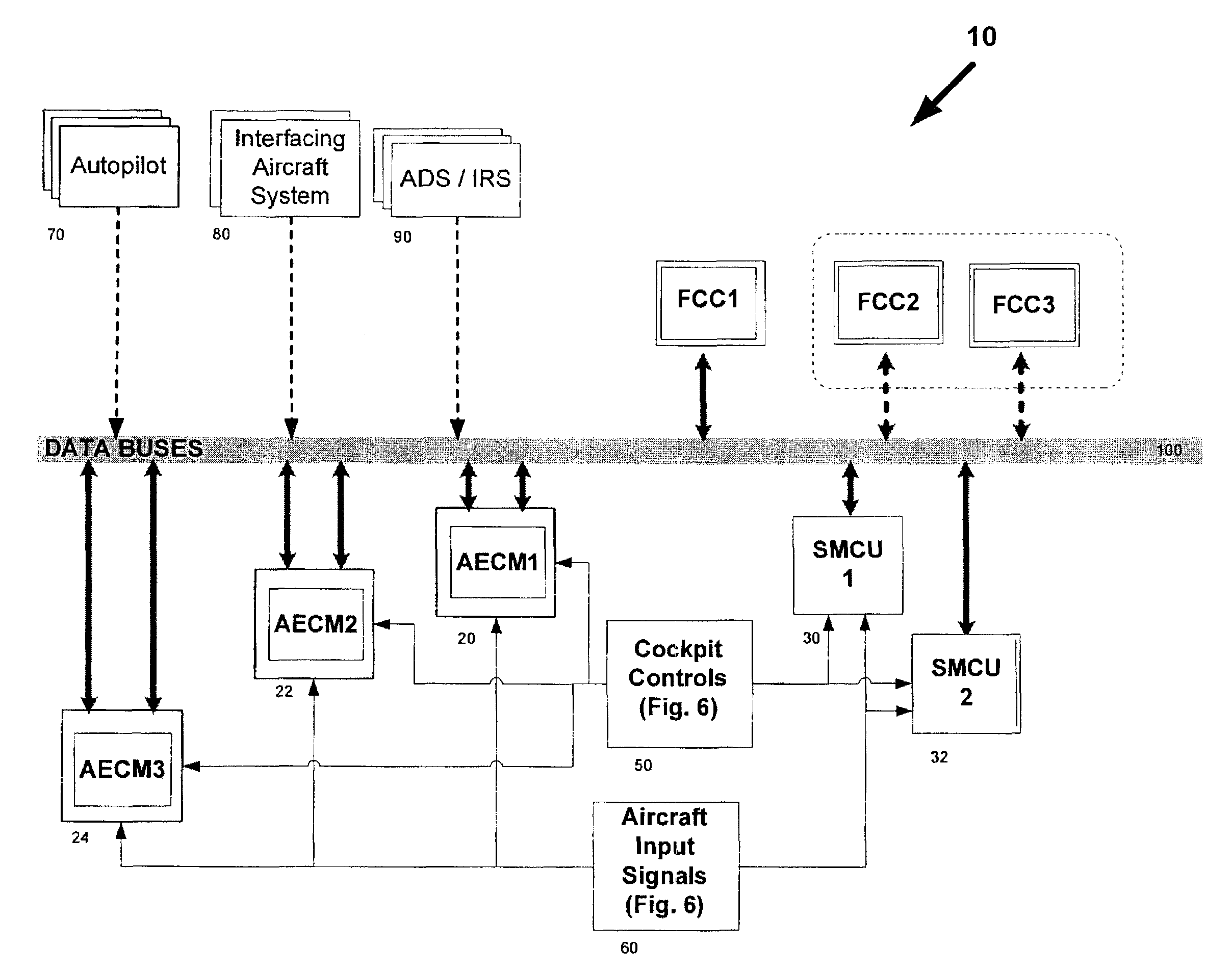
[0035]The flight control system of the present invention is a fly-by-wire multi-axis flight control system that is fault-isolated, fault tolerant, fail-safe and fail-operational. Its architecture and operational details will be discussed in detail below in the context of an illustrative embodiment and with reference to the figures provided.

[0036]General Overview

[0037]The illustrative embodiment of the multi-axis serially redundant, single channel, multi-path fly-by-wire flight control system (FCS) of the present invention includes a single control channel architecture based on serially redundant flight computers and comprising within the channel a plurality of control paths each with its own dissimilar hardware flight control surface controllers, which paths together, in the single channel, provide manual and automatic control of the aircraft in each of the pitch, roll and yaw axes through a matrix of complementary distributed control surfaces responsive to commands generated by the...


PUM


Abstract

A multi-axis serially redundant, single channel, multi-path fly-by-wire control system comprising: serially redundant flight control computers in a single channel where only one “primary” flight control computer is active and controlling at any given time; a matrix of parallel flight control surface controllers including stabilizer motor control units (SMCU) and actuator electronics control modules (AECM) define multiple control paths within the single channel, each implemented with dissimilar hardware and which each control the movement of a distributed set of flight control surfaces on the aircraft in response to flight control surface commands of the primary flight control computer; and a set of (pilot and co-pilot) controls and aircraft surface/reference/navigation sensors and systems which provide input to a primary flight control computer and are used to generate the flight control surface commands to control the aircraft in flight in accordance with the control law algorithms implemented in the flight control computers.

Description

FIELD OF THE INVENTION[0001]The present invention generally relates to aircraft control systems and, in particular, to a multi-axis serially redundant, single channel, multi-path fly-by-wire flight control system.BACKGROUND OF THE INVENTION[0002]Fly-by-wire technology has provided a major advance in aircraft flight control systems.[0003]Mechanical flight control systems had been prevalent where the flight control surfaces on an aircraft were controlled using a system of cables, linkages and mechanical controls as the primary and usually only control paths. Only limited, basic mechanical failure mode contingency was possible in such systems.[0004]With the advent of electronics and computer-aided flight controls, mechanical systems were given enhanced controllability through augmentation with, e.g., electrical drive assist and controls.[0005]Such improvements allowed for the development of advanced control laws that, among other things, improve and increase aircraft controllability an...

Claims


Application Information

Patent Timeline
Patent Type & Authority Applications(United States)
IPC IPC(8): G05D1/08G05D1/00
CPCB64C13/503B64C19/00G05D1/0077G05B9/03
Inventor LIN, SHUSMITH, TIMOTHYDE SERRES, PIERRE
Owner BOMBARDIER CORP
Why Eureka
Try Eureka