Access Control Device for a Door

a technology for access control devices and doors, which is applied to door/window accessories, wing knobs, wing accessories, etc., can solve the problems of user memory loss, door to be unlocked, and potentially allowing ingress from the outside, so as to simplify use and facilitate access

Active Publication Date: 2011-03-24
HANCHETT ENTRY SYST
View PDF36 Cites 25 Cited by
  • Summary
  • Abstract
  • Description
  • Claims
  • Application Information

AI Technical Summary

Benefits of technology

[0013]The system is intended for use on magnetically locked, non-fire rated doors. The addition of the mechanical switch actuation to the bar provides a new primary access function initiated by other than the capacitive human touch, which is expected to simplify use and ease accessibility for personnel with prosthetics or who may otherwise have their hands occupied (e.g. carrying boxes, manipulating carts, wheelchairs, etc.). In addition to capacitance-initiated touch sense function, mechanical movement of the bar is provided which is responsive to a lateral force as applied by any object (i.e. human hand pressure, hip, prosthesis, wheelchair, box, briefcase, etc.) to initiate activation of internal position detecting switches. The bar provides a release signal for as long as it senses capacitance from a human touch or by maintained mechanical switch actuation. The bar is fail safe (no power required) and a non-latching mechanical device.
[0014]The system allows re-securing of the door when the bar is released to allow the spring mechanism to return the bar to its original (at rest) position, thus disengaging the position detecting switches and when the human hand is totally disengaged from the bar.

Problems solved by technology

A shortcoming of the disclosed system is that the capacitive sensor output signal can be corrupted by electronic noise, causing the door to become unlocked when not intended and potentially allowing ingress from the outside.
A user may not know of the push button switch, or a user may not remember the position of the push button switch or how the switch may be activated, especially in this system since the switch is concealed behind the push bar.
Forces in this high range may be beyond the capabilities of a user in a given situation.
Further, the disclosed electromechanical force sensors use force sensing resistors whose sensitivity and output may change with aging of the sensors or of the associated actuating padding material.

Method used


Image

  • Access Control Device for a Door
  • Access Control Device for a Door
  • Access Control Device for a Door

Examples


Embodiment Construction

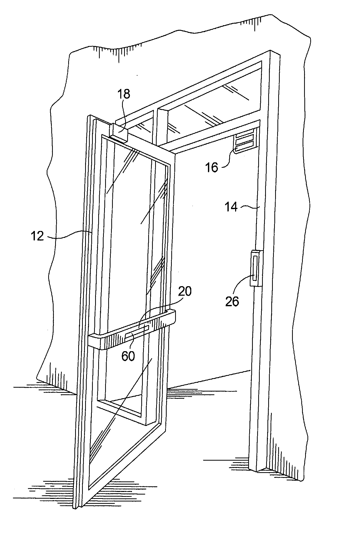
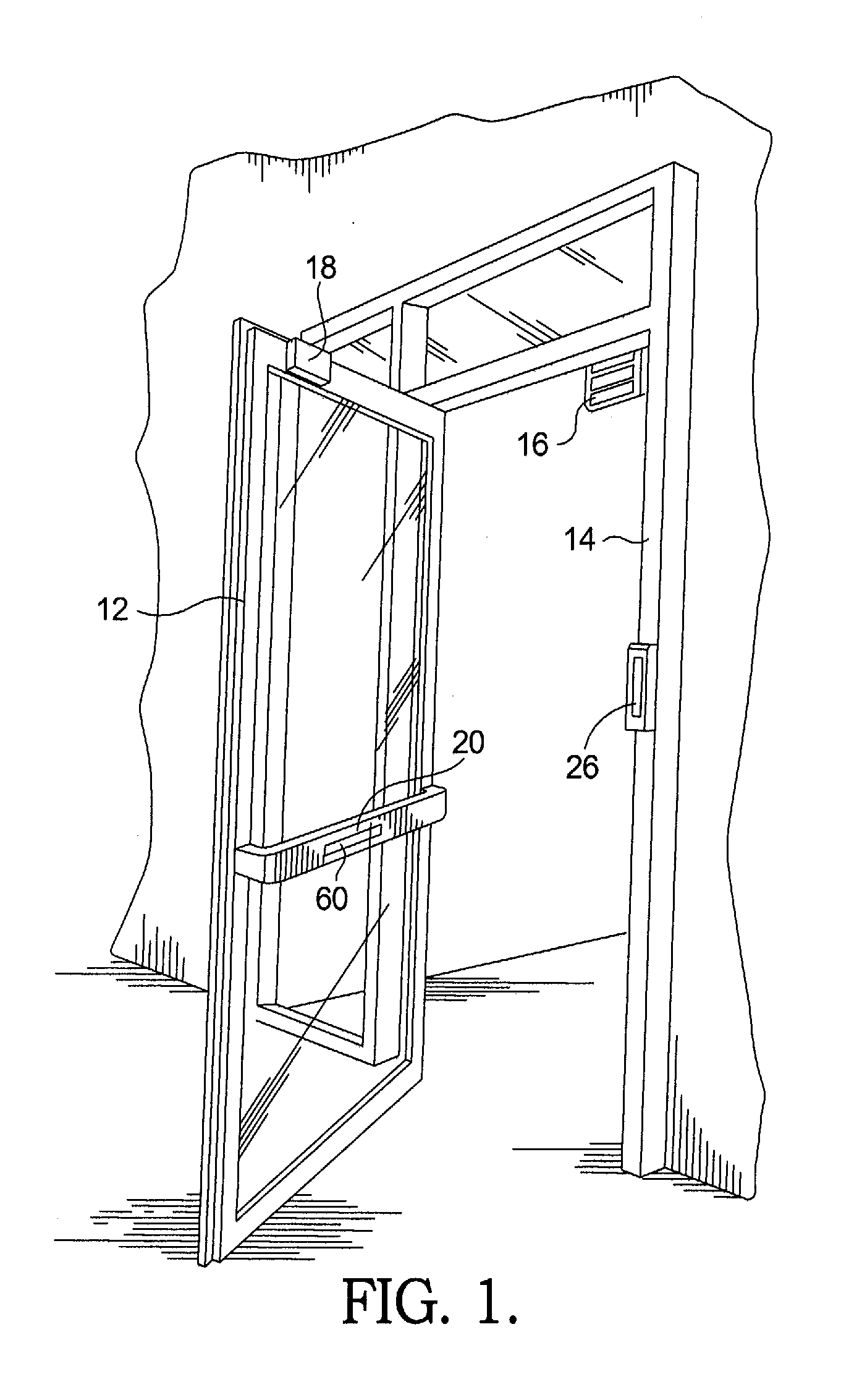
[0025]Referring to the drawings, FIG. 1 shows a door 12 and a door frame 14. Secured to the door frame is an electromagnet 16 which, together with the striker plate or armature 18 on the door forms an electromagnetic lock. On the inside of the door and mounted thereon is a door release system 20 in accordance with the present invention, mounted to door 12 by insulating blocks 22 used to electrically isolate the bar assembly from the door (FIGS. 2A, 2B and 3). In order to gain access to the interior of the secured area, inside door 12, a coded input panel 26 (FIG. 1) may be provided.

[0026]However, when egress from the secured area on the interior of the door 12 is desired, a person merely touches or pushes against system 20 and the result is to release the electromagnetic lock 16, 18, so that the door 12 may be pushed open.

[0027]The precise method of de-energization of the electromagnetic lock 16, 18, will be discussed in greater detail below.

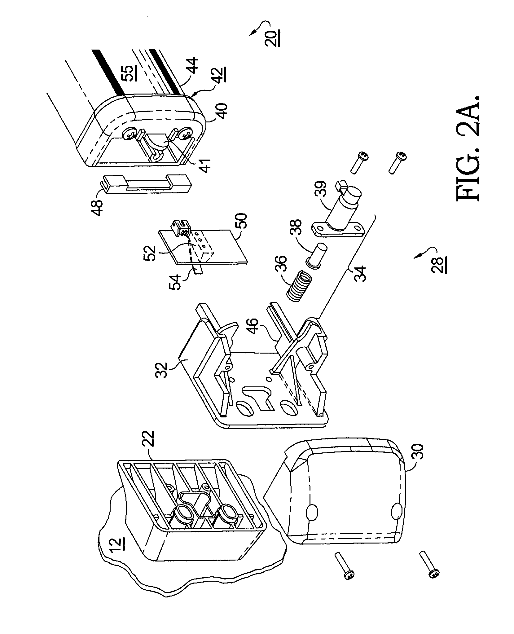
[0028]Referring to FIG. 2A, 2B and 3, an ...


PUM


Abstract

A door release system including a capacitive circuit that includes a touch bar, a microprocessor within the touch bar programmed with noise-discrimination software to sense touching of the bar, and at least one micro-switch within the bar to function as a back-up that picks up movement of the bar to release the latch should the capacitive circuit fail. Optionally, a sign illuminated by LEDs and an antimicrobial coating / treatment may be applied to the bar. The system is intended for use on magnetically locked doors. The addition of the micro-switches that are actuatable by continued movement on the touch bar after the bar is initially touched provides a redundant access function initiated by other than the capacitive effect of human touch, which is expected to simplify use and ease accessibility for personnel with prosthetics or who may otherwise have their hands occupied.

Description

REFERENCE TO PRIOR APPLICATIONS[0001]This application claims the benefit of U.S. Provisional Application 60 / 244,047, filed Sep. 20, 2009.TECHNICAL FIELD[0002]The present invention relates to releasable door access control devices; more particularly, to such devices having redundant release sensing mechanisms; and most particularly, to a device having a release bar that includes a microprocessor-controlled capacitive circuit to sense touching of the bar or proximity of an object to the bar and one or more micro-switches as back-up that pick up any slight movement of the bar so as to release the door should the capacitive circuit release feature be unresponsive.BACKGROUND OF THE INVENTION[0003]A requirement of magnetically-locked exit doors is that the magnetic lock be deactivatable from within a building upon demand by a user desiring egress. A typical exit door is provided with a horizontal electromagnetic lock-deactivating bar mounted across the inner surface of the door and respon...

Claims


Application Information

Patent Timeline
Patent Type & Authority Applications(United States)
IPC IPC(8): E05F15/20E06B7/00E06B7/28
CPCE05B1/0069E05B17/10E05C19/166E05B63/04E05B65/1053E05B17/22
Inventor HUNT, ROBERT C.KING, JONATHANCORWIN, JR., LARRY GENERODGERS, PAUL JUSTUS
Owner HANCHETT ENTRY SYST
Why Eureka
Try Eureka