Bus bar power distribution for an antenna embedded radio system

a radio system and antenna technology, applied in the direction of insulated conductors, cables, conductors, etc., can solve the problems of increasing the weight and cost of wires, high weight, and high cost of multi-layer laminates of the required size, so as to save weight and cost, save further weight, and reduce the thickness

a radio system and antenna technology, applied in the direction of insulated conductors, cables, conductors, etc., can solve the problems of increasing the weight and cost of wires, high weight, and high cost of multi-layer laminates of the required size, so as to save weight and cost, save further weight, and reduce the thickness

US20110068623A1Active Publication Date: 2011-03-24TELEFON AB LM ERICSSON (PUBL)

Image

  • Bus bar power distribution for an antenna embedded radio system
  • Bus bar power distribution for an antenna embedded radio system
  • Bus bar power distribution for an antenna embedded radio system

Examples


Embodiment Construction

[0033]The invention will now be described on the basis of the drawings. It will be understood that the embodiments and aspects of the invention described herein are only examples and do not limit the protective scope of the claims in any way. The invention is defined by the claims and their equivalents. It will also be understood that a feature of one aspect can be combined with the features of another aspect or other aspects.

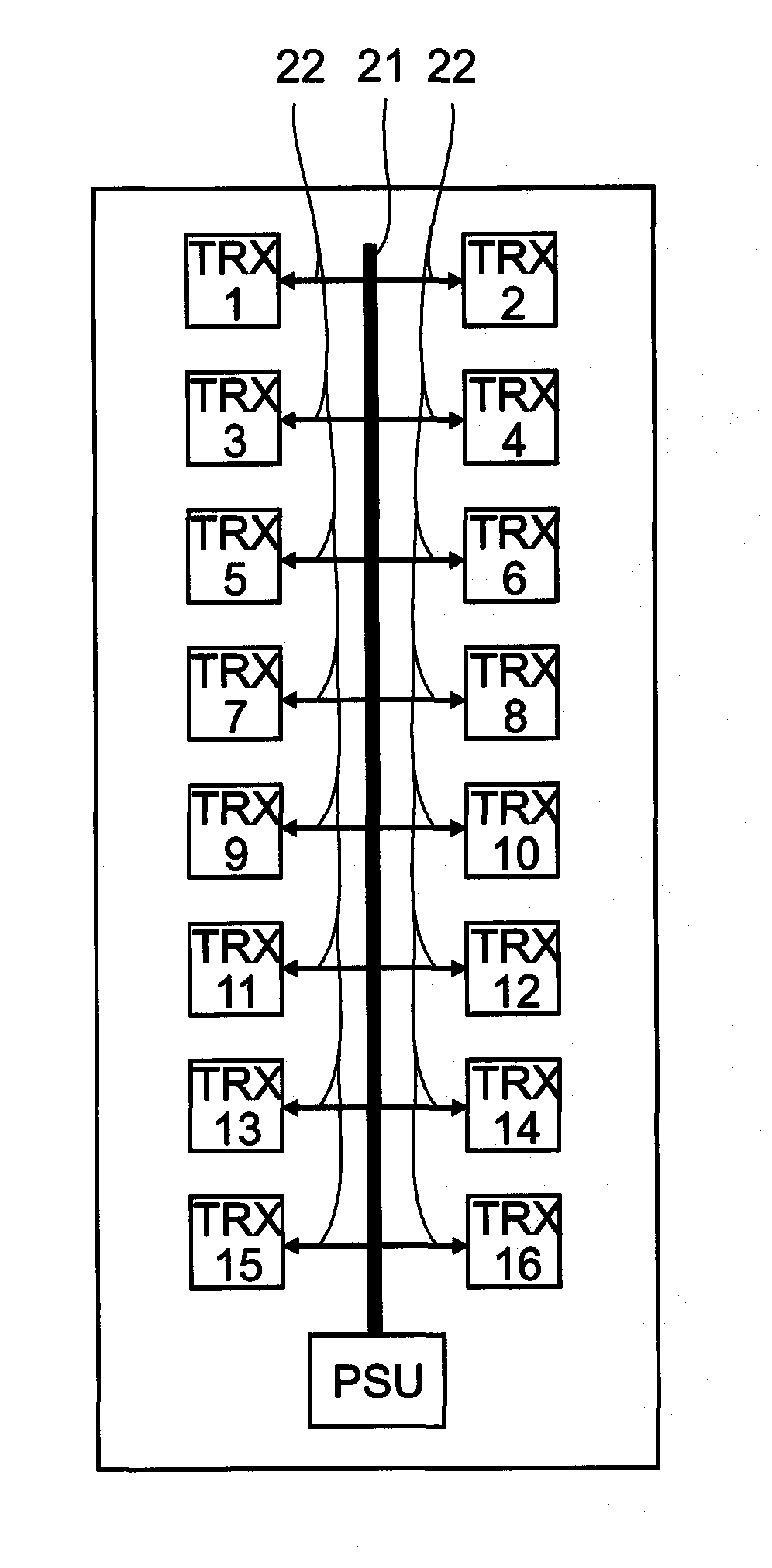
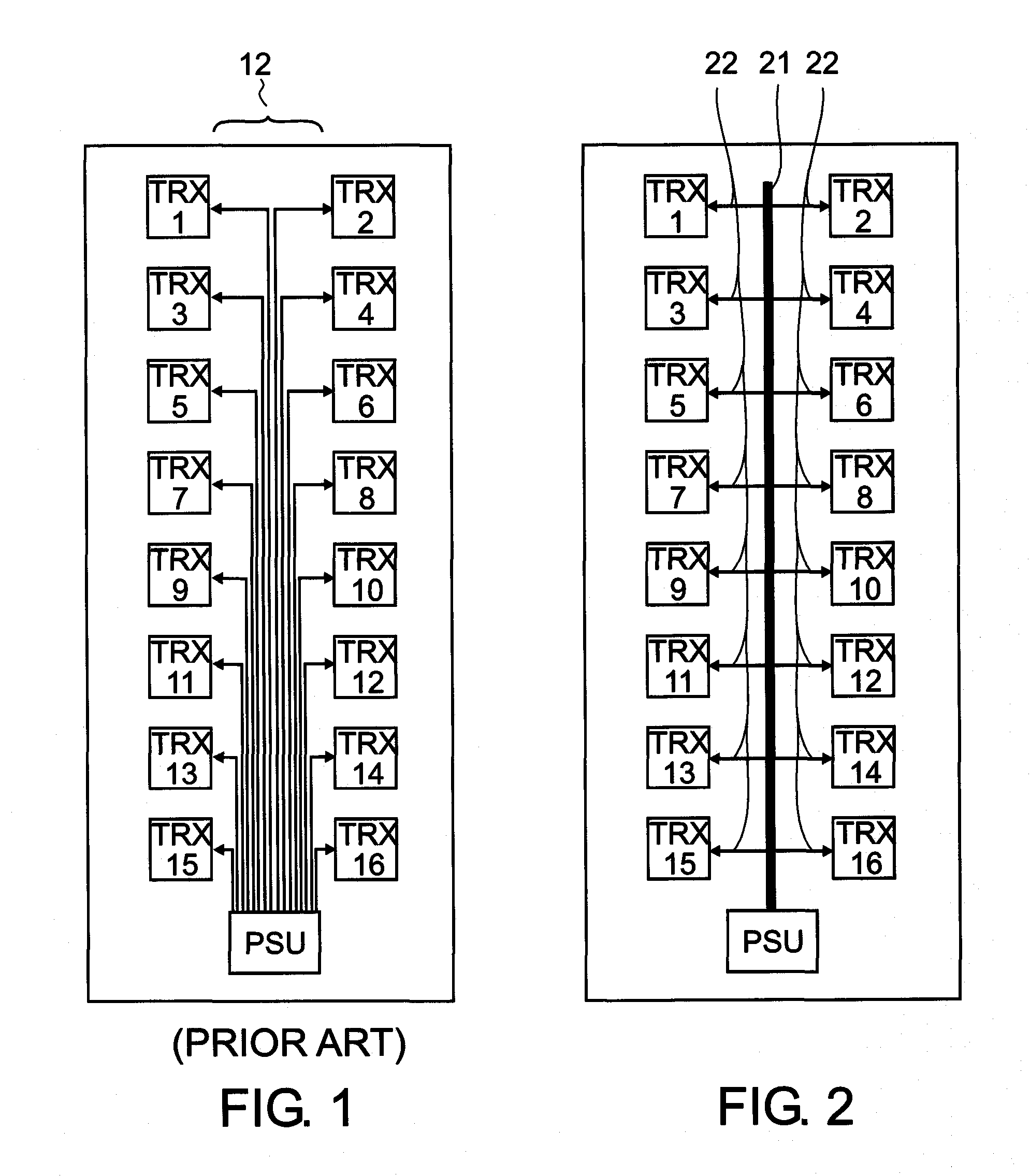
[0034]FIG. 1 shows an existing method of distributing power within an adaptive antenna or antenna-embedded radio system. FIG. 1 shows in a schematic manner a 2-by-8 array of 16 antenna embedded radios TRX1-TRX16. Each one of the active electronic circuits or transceivers TRX1-TRX16 is directly connected to a power supply unit PSU, typically via a pair of multi-strand, flexible cables 12—one of the multi-strand, flexible cables 12 is for the positive connection and an other one of the multi-strand, flexible cables 12 is for the negative or ground connection. Eac...


PUM


Abstract

A power distribution for an array of active electronic circuits in an antenna of a mobile communications base-station is disclosed. The power distribution comprises a first conductor connectable to a first terminal of a power supply unit, and a second conductor connectable to a second terminal of the power supply unit. The first conductor and the second conductor are at least partly bare and rigid, and are routed to the antenna-embedded radios in a manner separate from each other.

Description

FIELD OF THE INVENTION[0001]The field of the present invention relates to a power distribution, for example for use in an array of active electronic circuits within or adjacent to an antenna in a mobile communications base-station.BACKGROUND OF THE INVENTION[0002]Currently power distribution within an array of active electronic circuits located within or adjacent to an antenna is achieved using a “star” topology, i.e. a pair of wires (positive and ground) is connected from the power supply to each one of the active electronic circuits individually. For 16 antenna elements this results in 16 pairs of (relatively) high-current wires being required. These wires are also often flexible and therefore require insulating throughout their length which adds to the weight and cost of the wires.[0003]The European patent application 0 323 169 describes a power distribution system for a phased array radar. The power distribution system includes a large number of small capacitors, at least one pe...

Claims


Application Information

Patent Timeline
24 Mar 2011
Publication
US20110068623A1
IPC
H02J4/00
CPC
H02J1/08
Inventors
KENINGTON, PETER