
Direction finding method and device

Active Publication Date: 2011-03-24
HISEP TECH
View PDF3 Cites 16 Cited by
  • Summary
  • Abstract
  • Description
  • Claims
  • Application Information

AI Technical Summary

Benefits of technology

[0020]Other objects and advantages of the invention will become apparent as the description proceeds

Problems solved by technology

One of the major challenges all direction-finding techniques face, in most situations, but mainly within a reflective environment, is to overcome the multipath reflections problem.
Multipath reflections can cause false indications regarding the direction of the targeted RF source.
In prior art direction finding techniques that are based on measuring the signals amplitude, phase, or time of arrival, these multi-path reflections cause sever errors in the direction finding.
All said prior art techniques rely on one or more properties of the received signal, and therefore require relatively complicated calculations and analysis, and are also relatively expensive.
Therefore, said techniques are generally not suitable for small size and relatively simple wireless personal devices, such as cellular phones, PDAs, digital cameras, remote-control devices.
Furthermore, in many cases such devices comprise of only one receiving channel for each antenna, and therefore are not suitable for using the abovementioned prior art techniques, unless significantly increasing their size, and or price.
However, this tag reader / writer also uses signal strength and is therefore limited to RSSI protocols.
However, this technique (intended to look for radar pulses) uses signal strength and therefore requires many directional antennas and is limited to RSSI protocols.

Method used


Image

  • Direction finding method and device
  • Direction finding method and device
  • Direction finding method and device

Examples


Embodiment Construction

Definition of Terms

[0052]“Wireless Communication”—refers to the transfer of information and / or data and / or packets (formatted blocks of data) of any type or level and / or voice over long or short distances without the use of electrical conductors or “wires” but via Radio waves, at any given frequency.[0053]“Wireless Communication Protocol and / or Standard”—shall refer to any protocol and / or standard used to conduct wireless communication, such as, but not limited to, wireless information technology, cellular communication (such as, but not limited to, GSM, GPRS, CDMA), wireless networks, WLAN computer communications, wireless networking standards, such as, IEEE 802.11), wireless personal area networks (WPAN) and wireless mesh networks. (it should be clearly noted that among such protocols, but not limited only to them, are Wi-Fi, Bluetooth, Wi-Max, ZigBee, Z-wave, Insteon, cellular devices communication protocols, Near-Field Communication (NFC), RFID protocols or standards, etc.[0054]...


PUM


Abstract

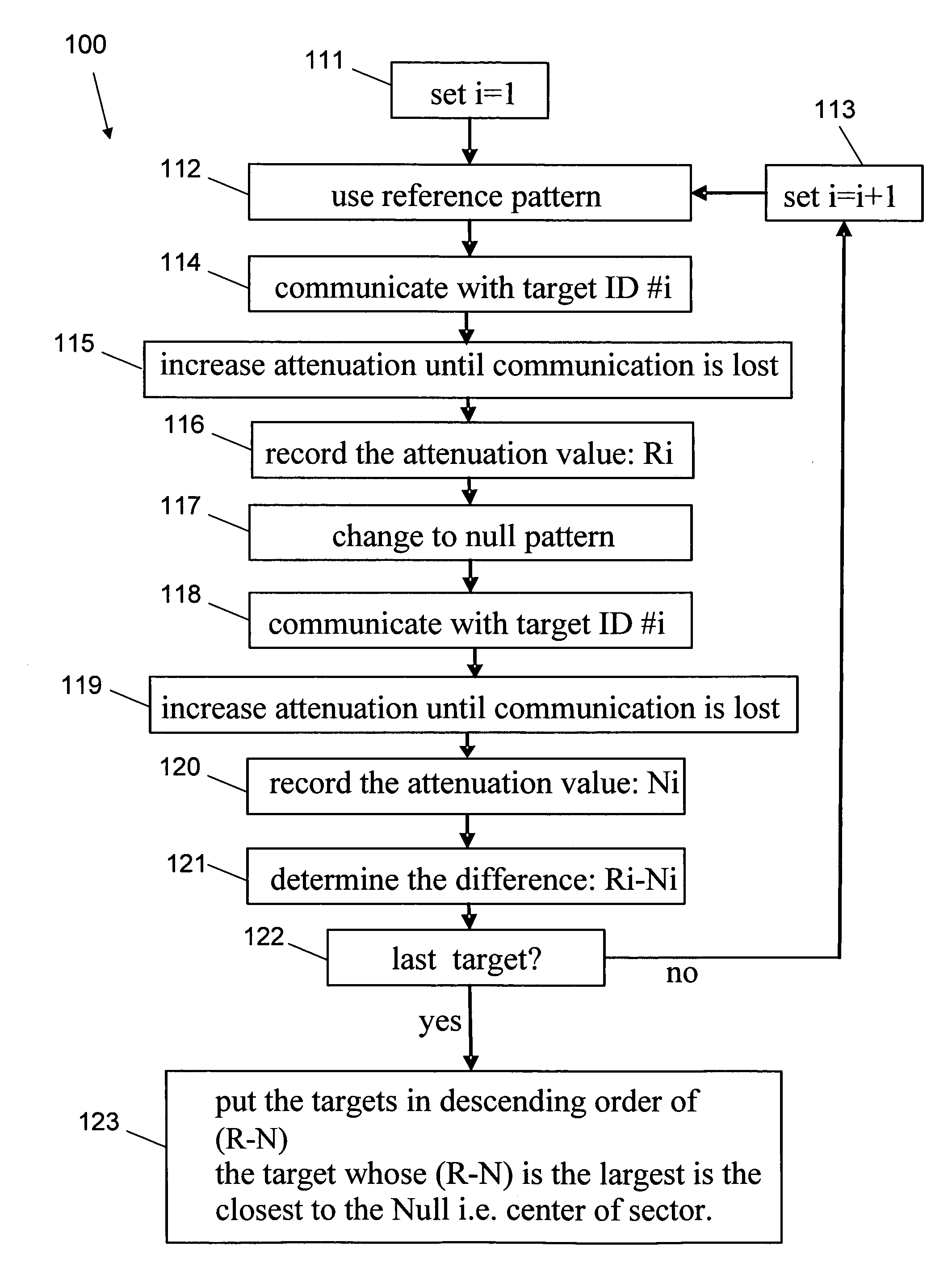
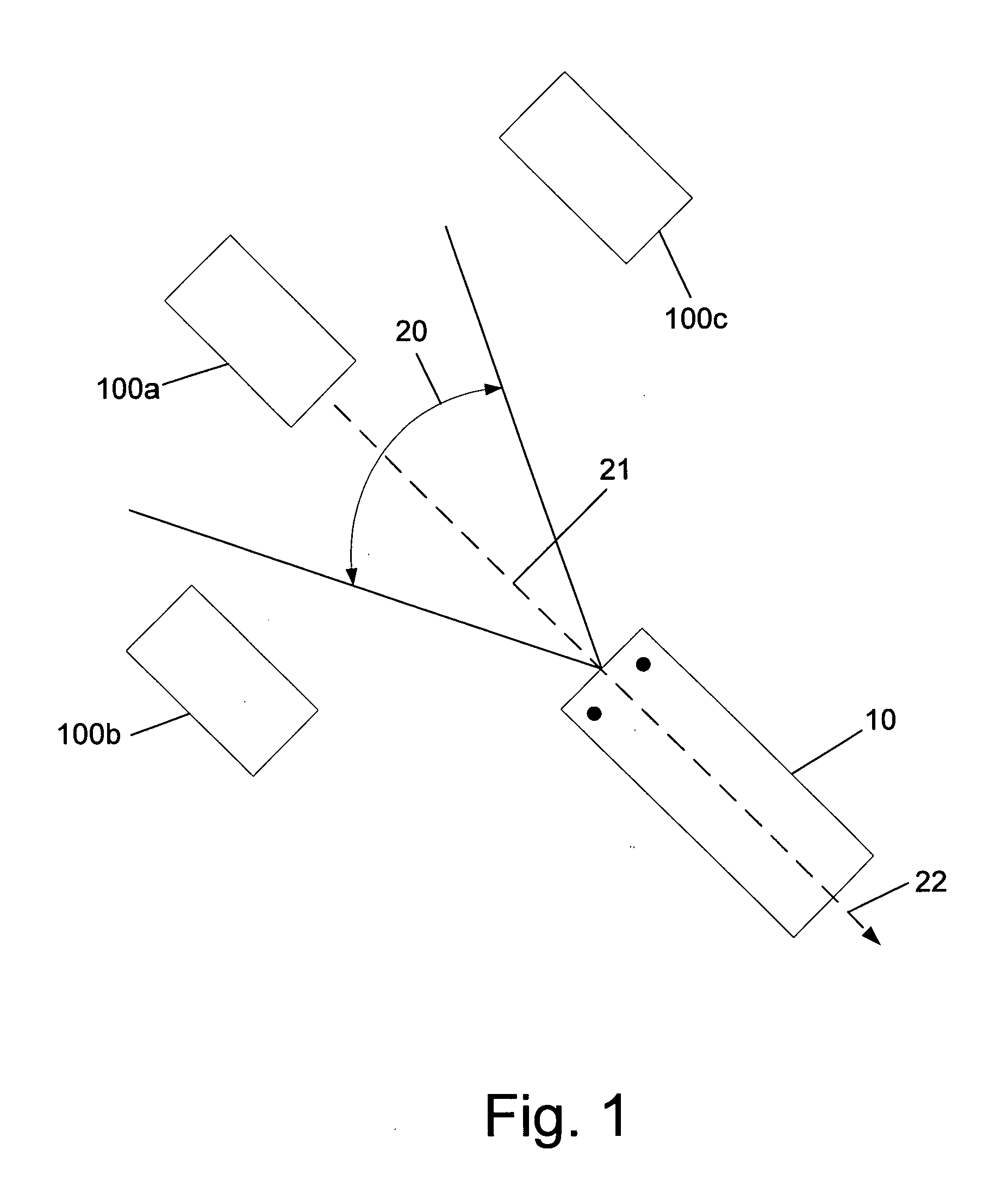
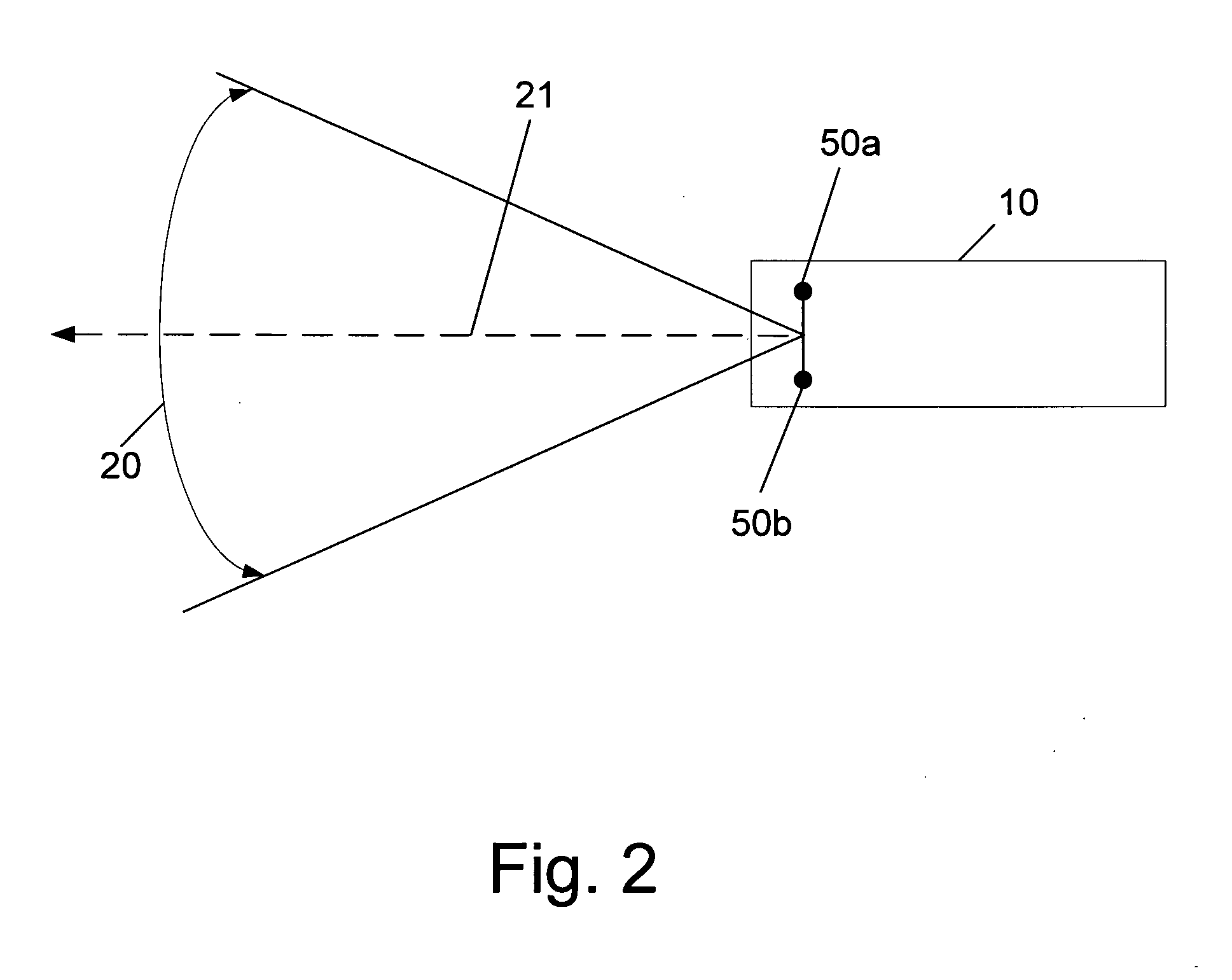
The invention relates to a method for determining whether a target is within a direction sector of interest of a direction finder, which comprises: (a) predefining said sector of interest as a specific threshold difference between an R reference value and an N null value; (b) providing at least two antennas arranged in a broad-side configuration within the direction finder; (c) generating an in-phase reference pattern using at least one of said antennas, and establishing wireless communication between the direction finder and said target; (d) attenuating the wireless communication signal between the direction finder and said target until the wireless communication is lost, and recording the attenuation value which corresponds to said loss of wireless communication as the R reference value; (e) generating an out-of-phase null pattern using at least two of said antennas, and re-establishing wireless communication between the direction finder and said target; (f) attenuating the wireless communication signal between the direction finder and said target until the wireless communication is lost, and recording the attenuation value which corresponds to said loss of wireless communication as the N null value; (g) determining whether the difference R−N is above or below said threshold difference, wherein a difference R−N above said threshold is an indication that the target is within said direction sector of interest, and wherein a difference R−N below said threshold is an indication that the target is out of said direction sector of interest. The invention also relates to a device for carrying out said method.

Description

FIELD OF THE INVENTION[0001]The present invention relates to the field of determining the direction to a wireless communication source. More particularly, the invention relates to a system and method for finding the direction to one or more wireless communication sources by aiming and pointing a direction finder or by scanning various directions relative to the pointing direction of the direction-finding device.BACKGROUND OF THE INVENTION[0002]The art has provided many ways for a direction finder (DF) to determine the direction to an RF source (target), mainly by various wave analysis procedures.[0003]Direction finding techniques can be categorized in groups, those which find the direction of the target based on the received signal amplitude, based on the received signal phase, based on received signal timing, or those which are based on several of said attributes of the received signal.[0004]One of the major challenges all direction-finding techniques face, in most situations, but ...

Claims


Application Information

Patent Timeline
IPC IPC(8): G01S3/20
CPCG01S3/043H01Q25/02G01S3/20
Inventor VERED, URIERAD, YARIVVERED, GAD
Owner HISEP TECH
Learn More