Laser pointing mechanism

a laser pointer and laser pointer technology, applied in measurement devices, active open surveying means, instruments, etc., can solve the problems of beam drooping or rising from its initial position, distance information to be lost,

Inactive Publication Date: 2011-03-24
FARO TECH INC
View PDF9 Cites 76 Cited by
  • Summary
  • Abstract
  • Description
  • Claims
  • Application Information

AI Technical Summary

Benefits of technology

[0015]At least one embodiment includes a pointing device for use with a laser tracker or laser scanner which may include a tracker or scanner control system and a tracker or scanner plant. The tracker plant may include a plurality of motors configured to apply a torque to a mechanism that steers the laser and a plurality of angular encoders configured to send feedback information on the angular position of the mechanism to the tracker control system. The tracker or scanner control system may be configured such that, when the pointing device is operating in a manual adjustment mode, the tracker or scanner control system controls the plurality of motors to provide a torque to the mechanism opposite to a direction of movement caused by the user.
[0016]An exemplary embodiment includes a pointing device for use with a laser device including a laser that emits a laser beam, the laser being positionable by a user, the pointing device including a control system, a plant operatively coupled to the control system including a plurality of motors configured to apply a torque to a mechanism that steers the laser, angular encoders configured to send feedback information on the angular position of the mechanism to the control system, a position sensing device configured to send information regarding the position of the laser beam on a surface of the position detector to the control system, a master control unit operatively coupled to the control system and the position sensing device, the master control unit including an encoder averager module configured to provide command position readings to the control system, a target positioner module configured to provide target position readings to the control system and a motion profiler module configured to generate command position readings to the control system.
[0017]Another exemplary embodiment includes a tracking pointing device for use with a laser tracker including a laser that emits a laser beam to be reflected off a retroreflector, the laser being positionable by a user, the tracking pointing device including a tracker control system and a tracker plant including motors having a zenith motor and an azimuth motor, the zenith motor and the azimuth motor being configured to apply a torque to a mechanism that steers the laser, angular encoders including a zenith angular encoder and an azimuth angular encoder, the zenith angular encoder and the azimuth angular encoder being configured to send feedback information on the angular position of the mechanism to the tracker control system and a position detector configured to send information regarding the position of the laser beam on a surface of the position detector to the tracker control system.
[0018]A further exemplary embodiment includes a scanning pointing device for use with a laser scanner including a laser that emits a laser beam, the laser being positionable by a user, the scanning pointing device including a scanner control system and a scanner plant including a motors having a zenith motor and an azimuth motor, the zenith motor and the azimuth motor being configured to apply a torque to a mechanism that steers the laser and angular encoders including a zenith angular encoder and an azimuth angular encoder, the zenith angular encoder and the azimuth angular encoder being configured to send feedback information on the angular position of the mechanism to the scanner control system.

Problems solved by technology

If the beam is broken during the measurement, the number of counts cannot be accurately known, causing the distance information to be lost.
Laser trackers have the ability to follow (track) a rapidly moving retroreflector, but scanners do not usually have this ability.
If the gimbal mechanism is unbalanced to even the slightest degree, however, the beam will tend to droop or rise from its initial position.

Method used


Image

  • Laser pointing mechanism
  • Laser pointing mechanism
  • Laser pointing mechanism

Examples


Embodiment Construction

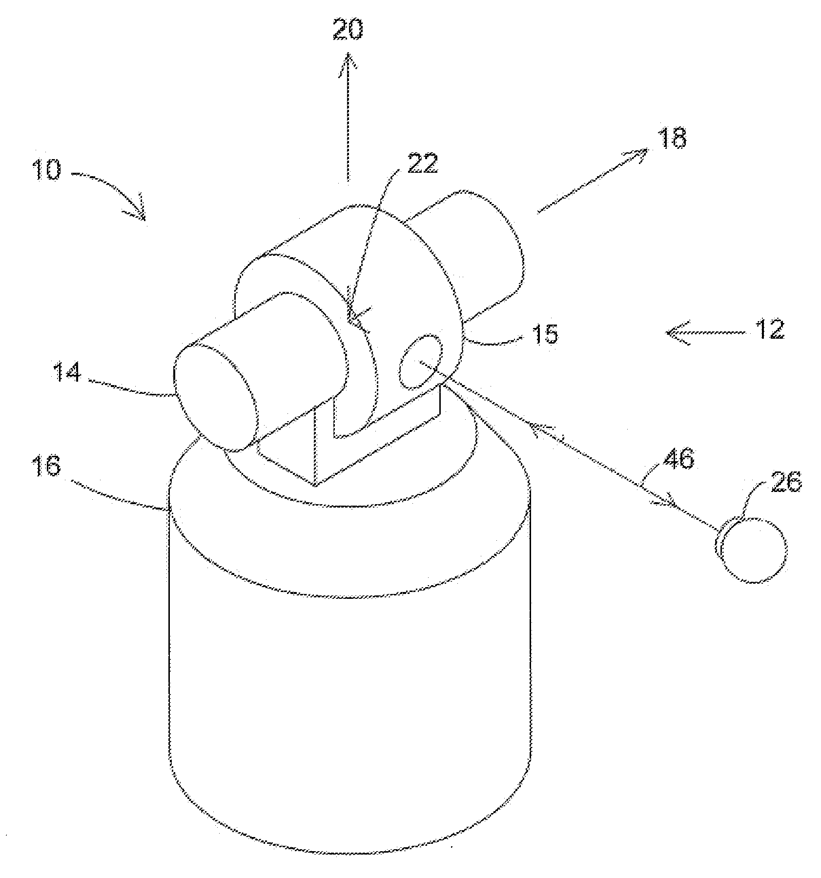
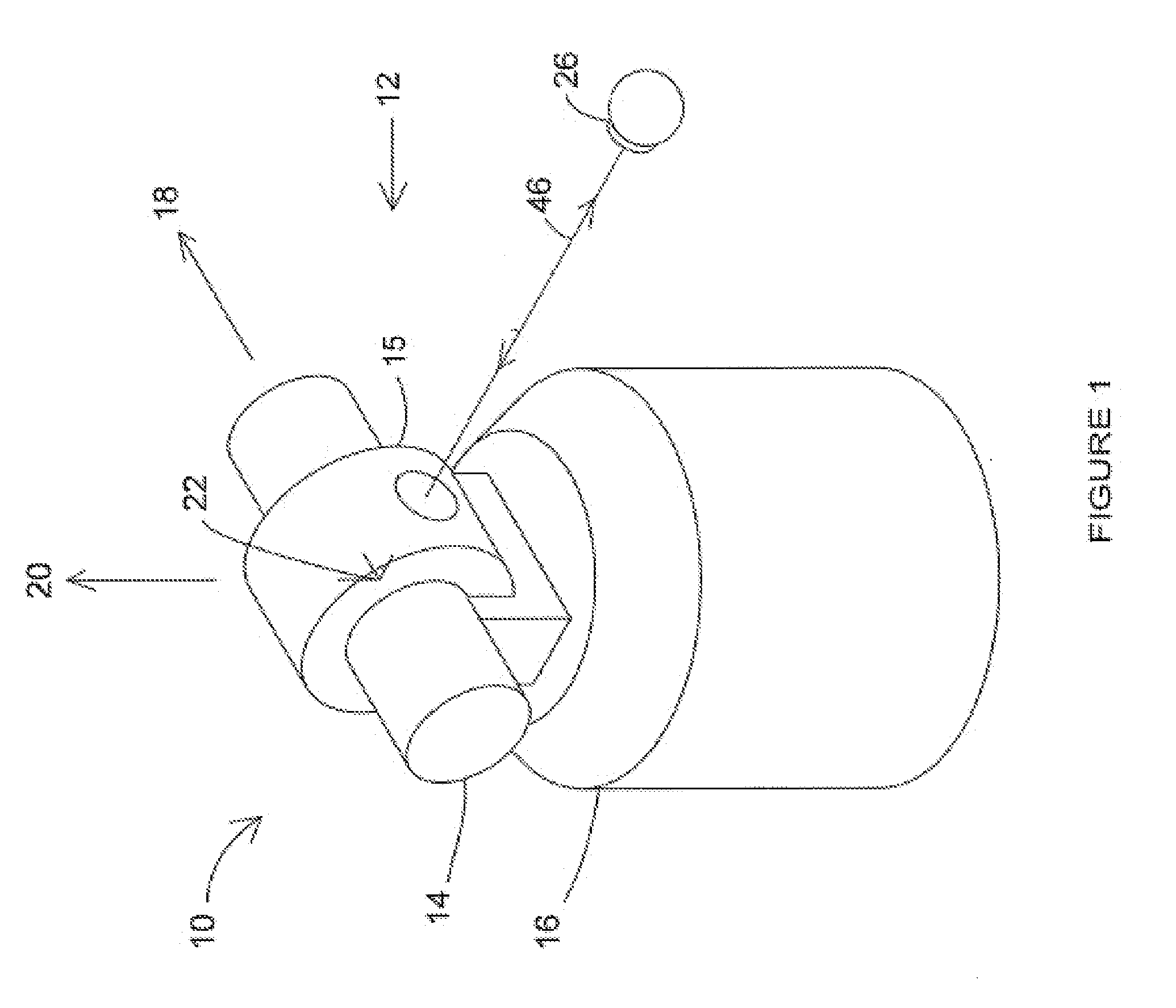
[0028]FIG. 1 shows a laser beam being sent from laser tracker 10 to SMR 26, which returns the laser beam to tracker 10. An exemplary gimbaled beam-steering mechanism 12 of laser tracker 10 includes zenith carriage 14 mounted on azimuth base 16 and rotated about azimuth axis 20. Payload 15 is mounted on zenith carriage 14 and rotated about zenith axis 18. Zenith mechanical rotation axis 18 and azimuth mechanical rotation axis 20 intersect orthogonally, internally to tracker 10, at gimbal point 22, which is typically the origin for distance measurements. Laser beam 46 virtually passes through gimbal point 22 and is pointed orthogonal to zenith axis 18. In other words, the path of laser beam 46 is in the plane normal to zenith axis 18. Laser beam 46 is pointed in the desired direction by rotation of payload 15 about zenith axis 18 and by rotation of zenith carriage 14 about azimuth axis 20. Zenith and azimuth angular encoders, internal to the tracker (not shown), are attached to zenith...


PUM


Abstract

A pointing device for use with a laser tracker or laser scanner may include a tracker or scanner control system and a tracker or scanner plant. The tracker plant may include a plurality of motors configured to apply a torque to a mechanism that steers the laser and a plurality of angular encoders configured to send feedback information on the angular position of the mechanism to the tracker control system. The tracker or scanner control system may be configured such that, when the pointing device is operating in a manual adjustment mode, the tracker or scanner control system controls the plurality of motors to provide a torque to the mechanism opposite to a direction of movement caused by the user.

Description

CROSS-REFERENCE TO RELATED APPLICATIONS[0001]This application claims the benefit of U.S. Provisional Application Ser. No. 61 / 244,380 entitled “LASER POINTING MECHANISM”, filed Sep. 21, 2009, which is incorporated herein by reference in its entirety.FIELD OF INVENTION[0002]The present invention relates to coordinate measuring devices, and more particularly to systems and methods configured to maintain a laser beam in a fixed direction after it has been manually pointed by the user.BACKGROUND[0003]One set of coordinate measurement devices belongs to a class of instruments that measure the three-dimensional (3D) coordinates of a point by sending a laser beam to the point, where it is intercepted by a retroreflector target. The instrument finds the coordinates of the point by measuring the distance and the two angles to the target. The distance is measured with a distance-measuring device such as an absolute distance meter or an interferometer. The angles are measured with an angle-meas...

Claims


Application Information

Patent Timeline
Patent Type & Authority Applications(United States)
IPC IPC(8): G01B11/14
CPCG01B11/002G01S17/66G01C15/004
Inventor HOFFER, JR., JOHN M.
Owner FARO TECH INC
Why Eureka
Try Eureka