

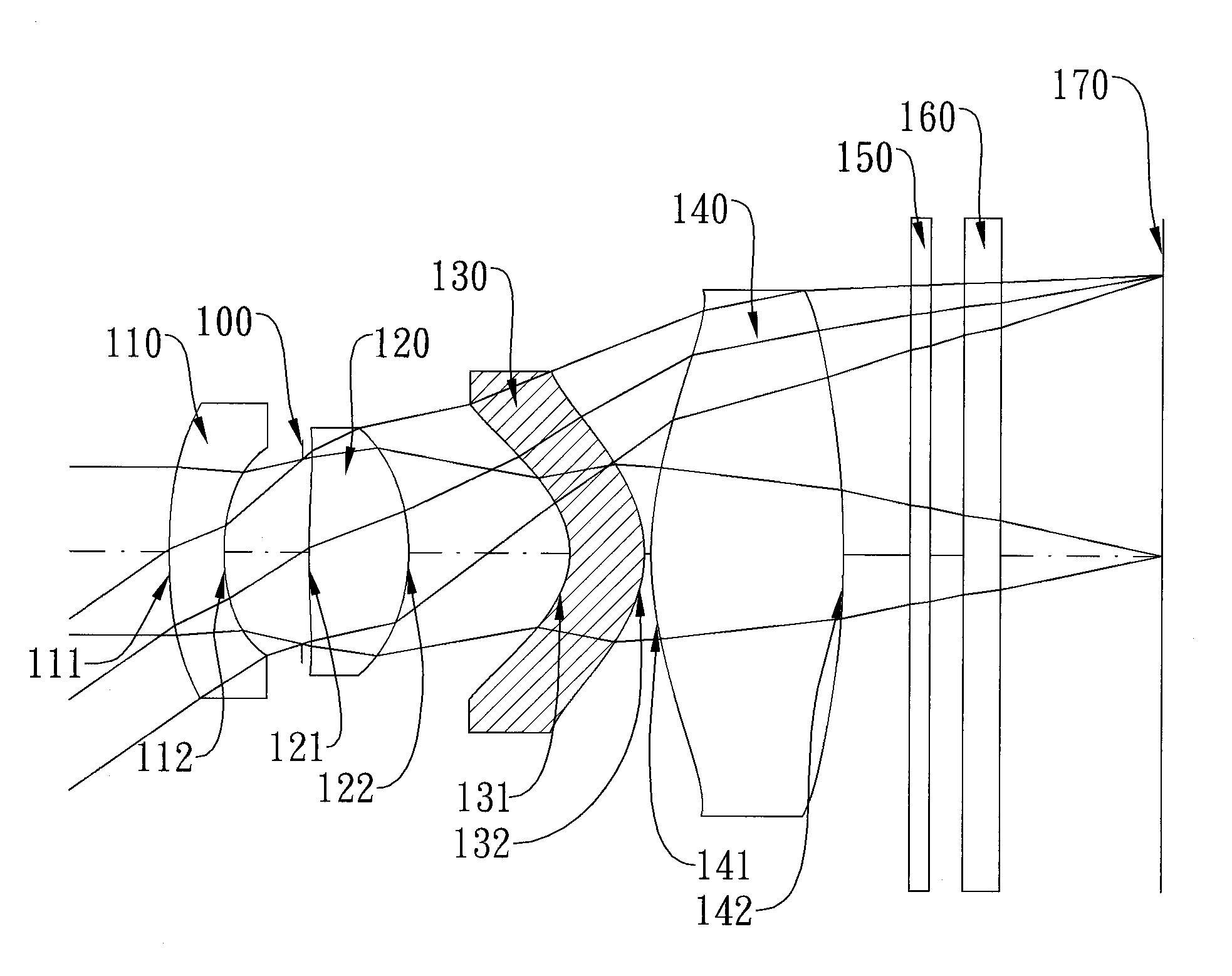
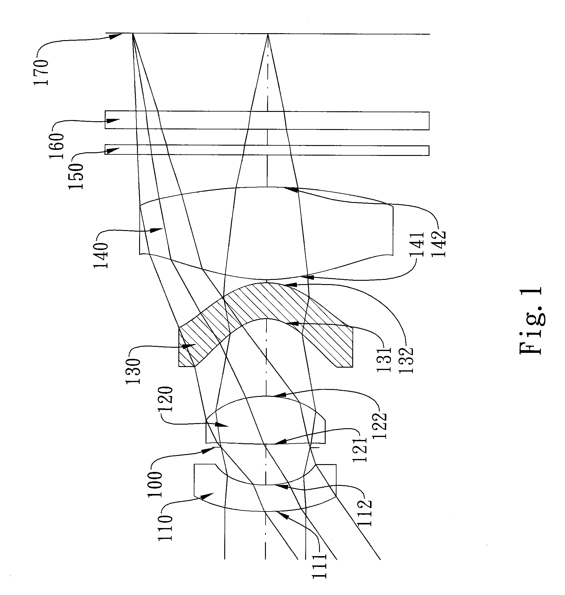
Near Infra-red Imaging Lens Assembly
a technology of infra-red and lens assembly, which is applied in the direction of optics, instruments, optical elements, etc., can solve the problems of increasing the increase of the total track length of the system, and the increase of the production cost. , to achieve the effect of reducing light interference and improving the response of the electronic photo sensor of the lens assembly
- Summary
- Abstract
- Description
- Claims
- Application Information
AI Technical Summary
Benefits of technology
Problems solved by technology
Method used
Image

Examples
first embodiment
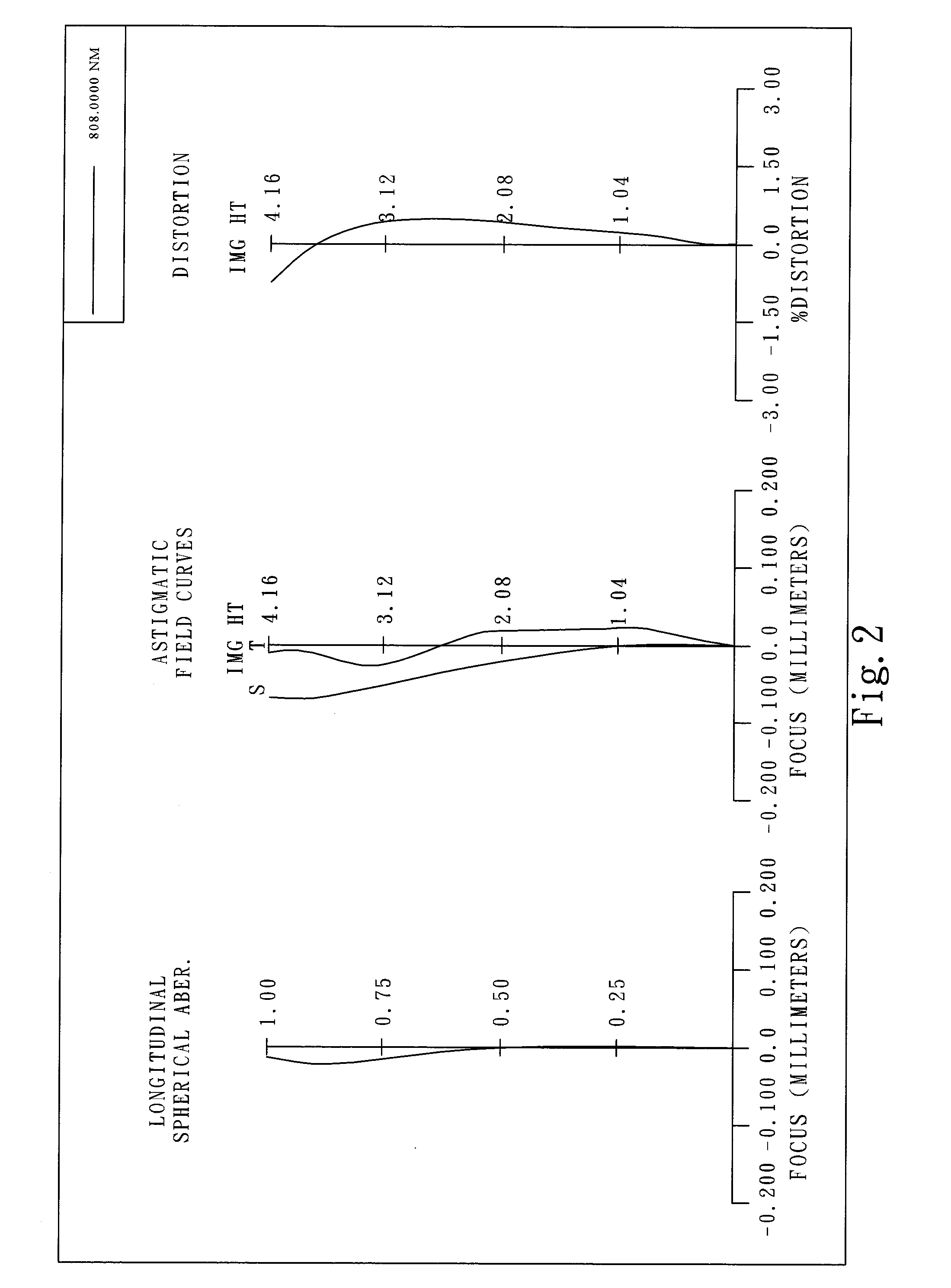
[0053]FIG. 3 is a modulation transfer function (MTF) chart of the present invention. MTF is a lens evaluation tool commonly used to evaluate the ability of a lens system to transform the contrast from object space to image space measured at different spatial frequencies, thereby evaluating the resolution, contrast and sharpness performances of the lens system. In FIG. 3, the x-axis of the chart represents the spatial frequency at which a test is carried out, and the y-axis represents the corresponding MTF of the lens system at said spatial frequencies; a higher value on the curve means better resolution power of the lens system.
[0054]FIG. 4 is the transmittance spectrum of the third lens element 130, which is made of a visible-light-absorbable material, in the first embodiment of the present invention. The x-axis of the chart represents the wavelength of the test light, and the y-axis represents the corresponding transmittance percentage of said lens element at said wavelength. As F...
second embodiment
[0066]FIG. 9 is an MTF chart of the present invention. MTF is a lens evaluation tool commonly used to evaluate the ability of a lens system to transform the contrast from object space to image space measured at different spatial frequencies, thereby evaluating the resolution, contrast and sharpness performances of the lens system. In FIG. 9, the x-axis of the chart represents the spatial frequency at which a test is carried out, and the y-axis represents the corresponding MTF of the lens system at said spatial frequencies; a higher value on the curve means better resolution power of the lens system.
[0067]In the second embodiment of the present NIR imaging lens assembly, the focal length of the entire assembly is f, and it satisfies the relation: f=5.98.
[0068]In the second embodiment of the present NIR imaging lens assembly, the f-number of the entire assembly is Fno, and it satisfies the relation: Fno=2.40.
[0069]In the second embodiment of the present NIR imaging lens assembly, half...
PUM
 Abstract
Description
Claims
Application Information