Surgical light

a light and surgical technology, applied in the field of surgical light, to achieve the effect of reducing the height of the main reflector and good reduction of colored shadows

Active Publication Date: 2011-03-24
STRYKER EURO OPERATIONS HLDG LLC
View PDF14 Cites 13 Cited by
  • Summary
  • Abstract
  • Description
  • Claims
  • Application Information

AI Technical Summary

Benefits of technology

[0006]It is the object of the present invention to further develop a surgical light with LEDs such that, with good thermal dissipation, a uniformly lit illuminated field can be produced which has as good as no shadow formation when a portion of the light incident onto the operating field is shaded by the surgeon.
[0010]In accordance with an advantageous embodiment, the LEDs can be arranged so that their light is coupled into the main reflector via at least one coupling reflector. In this embodiment, it is not necessary that the direction of radiation of the LEDs is directed radially or approximately radially to the optical axis of the main reflector. The light-emitting diodes can rather be arranged such that their radiation axes extend parallel or approximately parallel to the optical axis of the main reflector, which can contribute to a compact design of the light fixture and, on the other hand, allows an improved thermal dissipation of the LEDs in the direction of the light fixture side disposed opposite the light exit area.
[0016]A particularly good reduction in colored shadows can be achieved in that the LEDs are arranged at the outer margin of the main reflector such that two respective LEDs with different color temperatures are in each case disposed diametrically opposite one another.
[0017]In accordance with a further advantageous embodiment of the invention, at least two groups of LEDs can be provided at the outer margin of the main reflector, with the angle of incidence of the LEDs of the first group and the angle of incidence of the LEDs of the second group toward the optical axis of the main reflector being of different magnitude. This can be realized, for example, by a radial spacing of the LEDs toward the optical axis of the main reflector of different sizes or by a different angular position of the LED light sources toward the axis of the main reflector. In both cases, the advantage results that two illuminated fields of different size are produced by the two groups and lie concentrically to one another. An adaptation of the size of the illuminated field by proportional crossfading of the two illuminated fields is hereby possible by dimming the two LED groups.
[0018]In accordance with a further advantageous embodiment, the main reflector can have a section between two reflector zones or also facets which is orientated so that no light of the LEDs is reflected. This section thus does not contribute to the lighting of the operating field, but can be used to reduce the height of the main reflector in that the lower margin of a facet subsequent at distal to a facet is offset in the direction of the operating field.
[0020]Finally, it can be advantageous to couple the light of the LEDs in strip shape into the main reflector from the outer margin thereof, for example with the help of a bitoric lens or of a combination of a reflector and a two-stage optical system.

Problems solved by technology

What is problematic with known surgical lights of this type is, on the one hand, the heat development of the LEDs and, on the other hand, the uniform illumination of the operating field without colored shadow and without cast shadow formation.

Method used


Image

  • Surgical light
  • Surgical light
  • Surgical light

Examples


Embodiment Construction

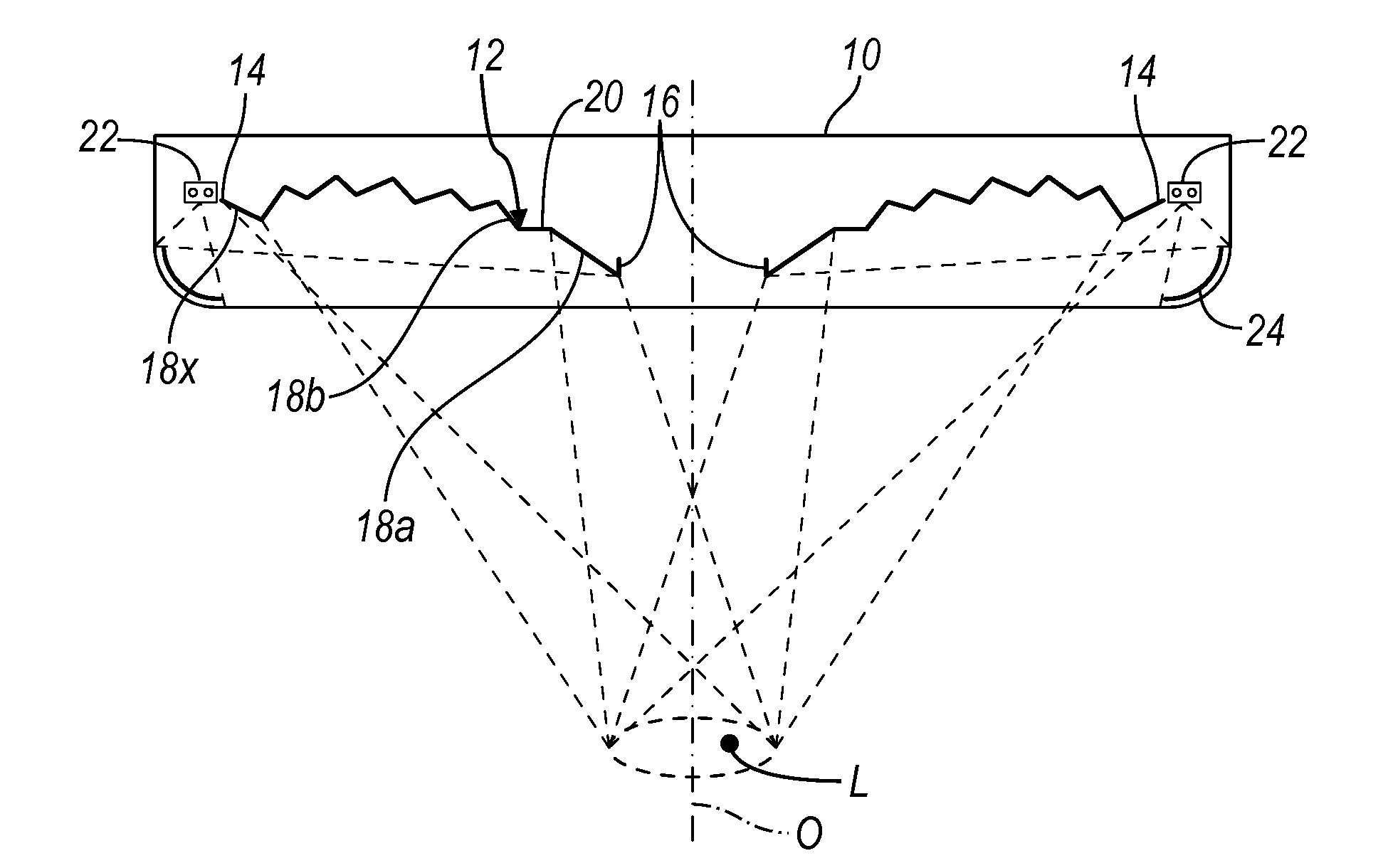
[0029]FIG. 1 shows a highly schematic cross-sectional view of a surgical light with a disk-like housing 10 in which a central main reflector 12 is arranged which has an optical axis 0 and an outer margin 14. In the embodiment shown, the main reflector 12 is made open in its central inner region so that this main reflector 12 also has an inner margin 16 which can be flowed through provided that corresponding throughflow openings are provided in the region of the housing 10. Alternatively, however, the main reflector 12 can also, as shown in FIG. 7, be made closed and have a central handle 15.

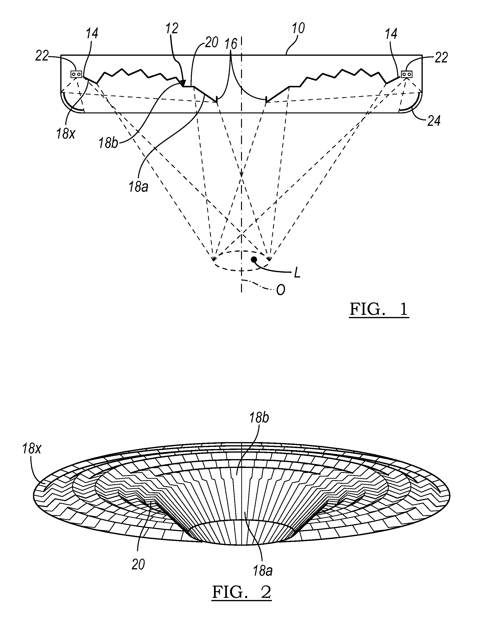
[0030]The main reflector 12 shown in FIG. 1 and also in the other Figures is—in contrast to a ring reflector or individual reflectors—made in areal form (cf. FIG. 2) and it can—as in the embodiment shown) be divided into a plurality of reflector zones or facets 18a, 18b, . . . , 18x, with the main reflector being made as a free-formed reflector and the individual facets being able to merge contin...


PUM


Abstract

A surgical light has a plurality of LEDs and a main reflector which directs the light of the LEDs onto an operating field. The main reflector is made in areal form and is divided into a plurality of reflector zones.

Description

CROSS-REFERENCE TO RELATED APPLICATIONS[0001]This application claims priority to co-pending German Patent Application Serial Number 10 2009 042 338.9, filed Sep. 21, 2009, the entirety of which is incorporated by reference herein.BACKGROUND OF THE INVENTION[0002]1. Field of the Invention[0003]The present invention relates to a surgical light with a reflector and a light source having a plurality of LEDs.[0004]2. The Prior Art[0005]Surgical lights which generate the light to be directed to the operating field with the help of LEDs are known in practice. What is problematic with known surgical lights of this type is, on the one hand, the heat development of the LEDs and, on the other hand, the uniform illumination of the operating field without colored shadow and without cast shadow formation.BRIEF DESCRIPTION OF THE INVENTION[0006]It is the object of the present invention to further develop a surgical light with LEDs such that, with good thermal dissipation, a uniformly lit illuminat...

Claims


Application Information

Patent Timeline
Patent Type & Authority Applications(United States)
IPC IPC(8): F21V7/00
CPCF21V7/0033F21V7/04F21W2131/205F21Y2103/022F21Y2113/005A61B2019/521F21Y2101/02A61B2090/309F21Y2115/10F21Y2103/33F21Y2113/13
Inventor JACOBI, LEIF
Owner STRYKER EURO OPERATIONS HLDG LLC
Why Eureka
Try Eureka