Method and apparatus for channel allocation in a visible light communication system

a communication system and channel technology, applied in the field of visible light communication (vlc), can solve the problems of data transmission between the two, difficult to achieve the effect of this condition, interference or even preventing the regular service, etc., and achieve the effect of efficient use of light sources

Active Publication Date: 2011-03-24
SAMSUNG ELECTRONICS CO LTD
View PDF4 Cites 57 Cited by
  • Summary
  • Abstract
  • Description
  • Claims
  • Application Information

AI Technical Summary

Benefits of technology

Another aspect of the present invention is to provide a VLC method and a VLC system capable of efficiently using the light sources of the VLC system.

Problems solved by technology

Among FIGS. 2A to 2C, FIG. 2B is an ideal condition, but it is difficult to actually achieve this condition.
However, when the light source 30 and the light source 40 provide different kinds of services, data transmitted by the two services can collide with each other in a collision region, interfering with or even preventing the regular service.
Further, normal VLC is not possible at all in the non-service area.
As such, in order to provide the conventional VLC by the adjacent multiple light sources, there is a limitation in that the adjacent multiple light sources have to provide all of the users with the same service.

Method used


Image

  • Method and apparatus for channel allocation in a visible light communication system
  • Method and apparatus for channel allocation in a visible light communication system
  • Method and apparatus for channel allocation in a visible light communication system

Examples


Embodiment Construction

Hereinafter, various embodiments of the present invention will be described with reference to the accompanying drawings. In the following description, the same elements will be designated by the same reference numerals although they are shown in different drawings. Further, various specific definitions found in the following description are provided only to help general understanding of the present invention, and it will be understood by those skilled in the art that various changes in form and details may be made therein without departing from the spirit and scope of the present invention.

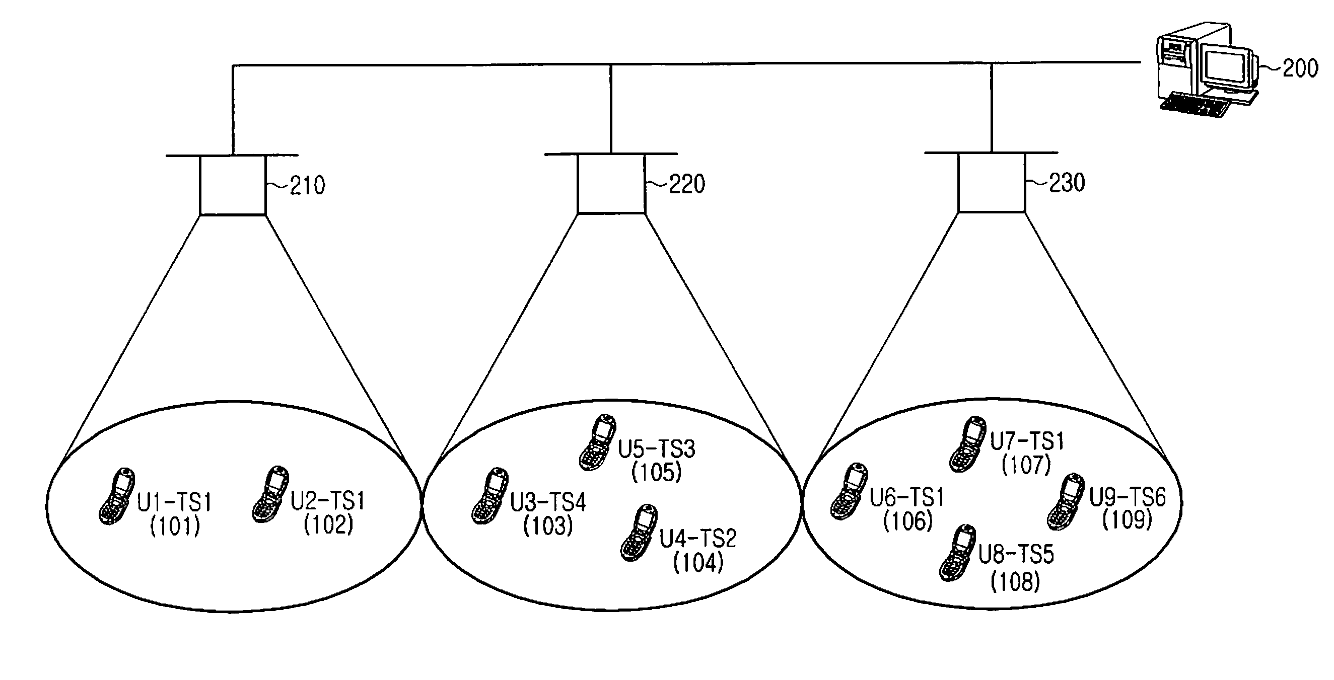
In accordance with an embodiment of the present invention, transmission of data by a VLC system uses a Time Division Multiplexing (TDM) scheme and a wavelength division multiplexing scheme. That is, according to an embodiment of the present invention, when different data is transmitted, a transmission frame is divided into multiple time slots and a transmission channel in the unit of the time slot...


PUM


Abstract

A method and apparatus for allocating resources of a Visible Light Communication (VLC) terminal in a VLC system. The VLC terminal receives a beacon message from a base station, coordinates time synchronization with the base station, searches for an available wavelength channel, constructs available wavelength channel information, and transmits an initial access request using a basic time slot channel and a basic wavelength channel. The base station considers the available wavelength channel information and a current channel allocation condition, allocates an appropriate channel, and transmits channel allocation information to the VLC terminal. The VLC terminal and the base station communicate data with each other using an allocated time slot channel included in the channel allocation information and an allocated wavelength channel included in the channel allocation information.

Description

PRIORITYThis application claims priority under 35 U.S.C. §119(a) to Korean Patent Applications filed in the Korean Industrial Property Office on Sep. 19, 2009 and Jan. 18, 2010, and assigned Serial Nos. 10-2009-0088786 and 10-2010-0004554, respectively, the contents of which are incorporated herein by references.BACKGROUND OF THE INVENTION1. Field of the InventionThe present invention relates generally to Visible Light Communication (VLC), and more particularly, to a method and an apparatus for allocating multiple channels in a VLC system.2. Description of the Related ArtCurrently, research into visible light wireless communication using a visible Light Emitting Diode (LED) is being conducted by various companies and laboratories.FIG. 1 illustrates a conventional VLC system.Referring to FIG. 1, the VLC system includes a light source 10, which includes an LED or a Laser Diode (LD). The light source 10 transmits and receives data using visible light, while simultaneously functioning a...

Claims


Application Information

Patent Timeline
Patent Type & Authority Applications(United States)
IPC IPC(8): H04J4/00H04J14/02H04B10/114H04B10/116
CPCH04B3/542H04B10/1149H04W72/08H04B2203/5441H04B10/116H04W72/54
Inventor KIM, DO-YOUNGWON, EUN-TAEBAE, TAE-HANGU, SUN-GISON, JAE-SEUNG
Owner SAMSUNG ELECTRONICS CO LTD
Why Eureka
Try Eureka