Connecting member

a technology of connecting member and photovoltaic cell module, which is applied in the direction of contact member penetrating/cutting insulation/cable strands, solar heat collector safety, lighting and heating apparatus, etc., can solve the problems of high installation cost, difficult installation, and difficulty in reducing the number of components, so as to reduce the number of components and simplify the installation time and effort. , the effect of reducing the cos

Active Publication Date: 2011-03-24
YANEGIJUTSUKENKYUJO CO LTD
View PDF31 Cites 72 Cited by
  • Summary
  • Abstract
  • Description
  • Claims
  • Application Information

AI Technical Summary

Benefits of technology

[0014]According to the present invention, for the predetermined member such as the photovoltaic cell module and the decorative cover fixed on the roof, a wall surface and the like in a state in which the end thereof is floating, the connecting member may be fitted to the ends of the sides facing the same direction in the adjacent predetermined members so as to sandwich the sides by the upper piece and the lower piece from outside from a direction perpendicular thereto, so that the sides facing the same direction may be joined in a substantially linear manner by the upper piece, the lower piece and the connecting piece, thereby eliminating the displacement between the predetermined members and making the appearance of the photovoltaic power generation system composed of a plurality photovoltaic cell modules excellent. Also, it is possible to eliminate the displacement between the ends only by fitting the connecting member to the ends of the adjacent predetermined members from outside from the direction perpendicular thereto, so that it is not required to adjust the displacement between the ends of the predetermined members by putting the spacer and the like below the fixing member for fixing the photovoltaic cell module to the predetermined supporting member and the time and effort in installing the photovoltaic cell module may be simplified and the cost may be reduced.
[0027]In this manner, according to the present invention, it is possible to provide the connecting member capable of eliminating the displacement between the ends, preventing the cost of the installation from increasing and obtaining the excellent appearance of the installed photovoltaic cell module only by being attached to the ends of the predetermined members such as the photovoltaic cell module and the decorative cover.

Problems solved by technology

However, in Patent document 1, it is necessary to attach the mount on the roof at a predetermined interval in advance according to a size of the photovoltaic cell module, and so that it takes increased time and effort for installation of the photovoltaic cell module.
As a result, there is a problem that the cost of installation increases highly.
Therefore, when a plurality of photovoltaic cell modules are installed so as to be arranged in a planar manner, depending on a state of the roof board, a roof material and the like as the supporting member to which the fixing member is attached, displacement (especially displacement in a direction perpendicular to a surface of the supporting member) occurs between the ends of the adjacent photovoltaic cell modules and appearance of a photovoltaic power generation system composed of a plurality of photovoltaic cell modules becomes problematically bad.
Also, when the above-described displacement is found after the installation of the photovoltaic cell modules (or after attachment of the fixing member to the supporting member), it is necessary to remove once the fixing member from the supporting member, put a spacer and the like below the fixing member and attach again the fixing member, so that there is a problem of increased installation cost, and since attaching strength of the fixing member might be deteriorated depending on the material of the supporting member when the fixing member once attached is fixed again on the same position, the fixing member, that is to say, the photovoltaic cell module might not be installed in an optimal state.

Method used


Image

  • Connecting member
  • Connecting member
  • Connecting member

Examples


Embodiment Construction

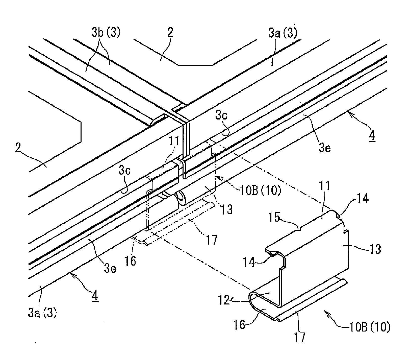
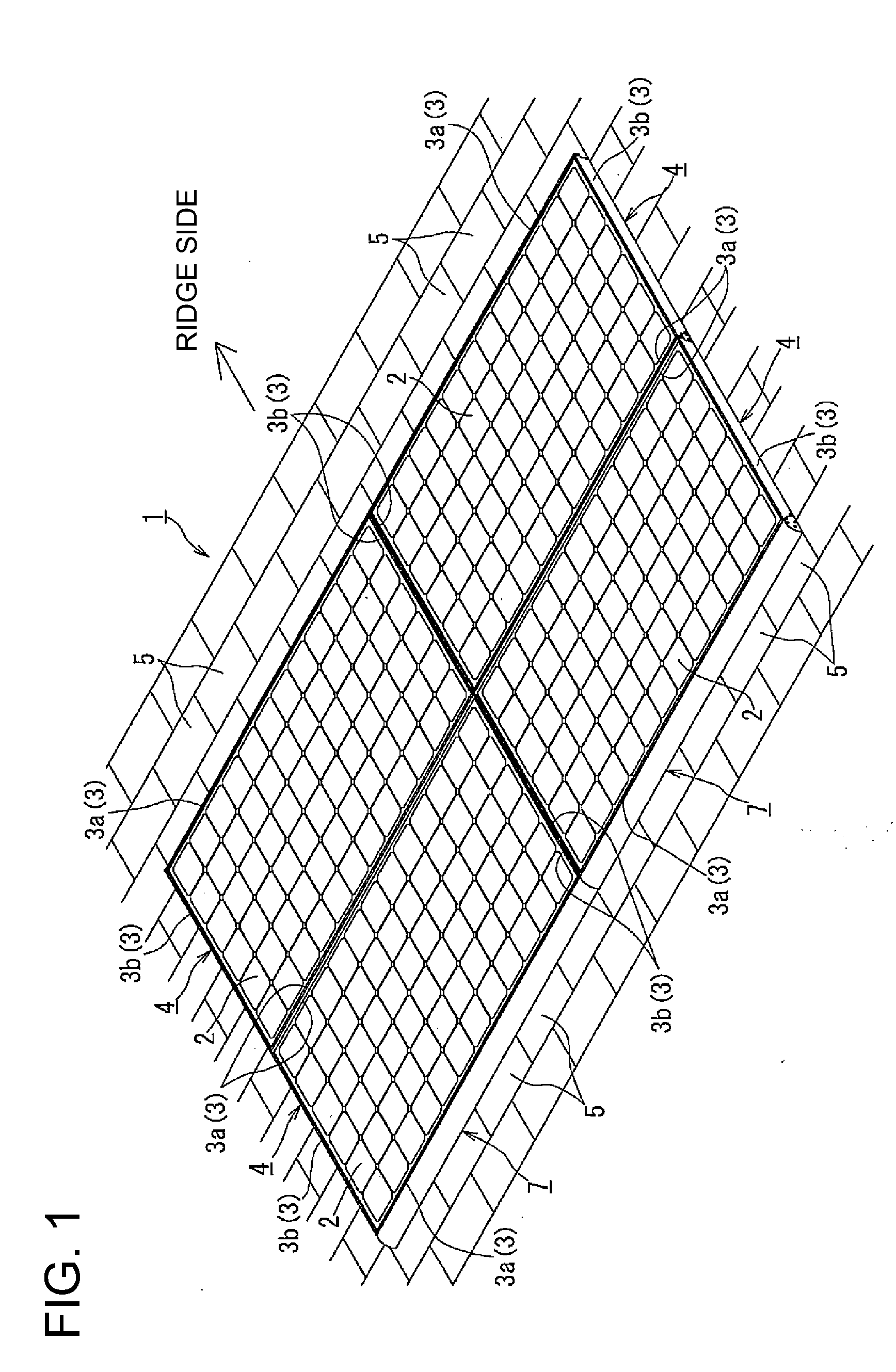
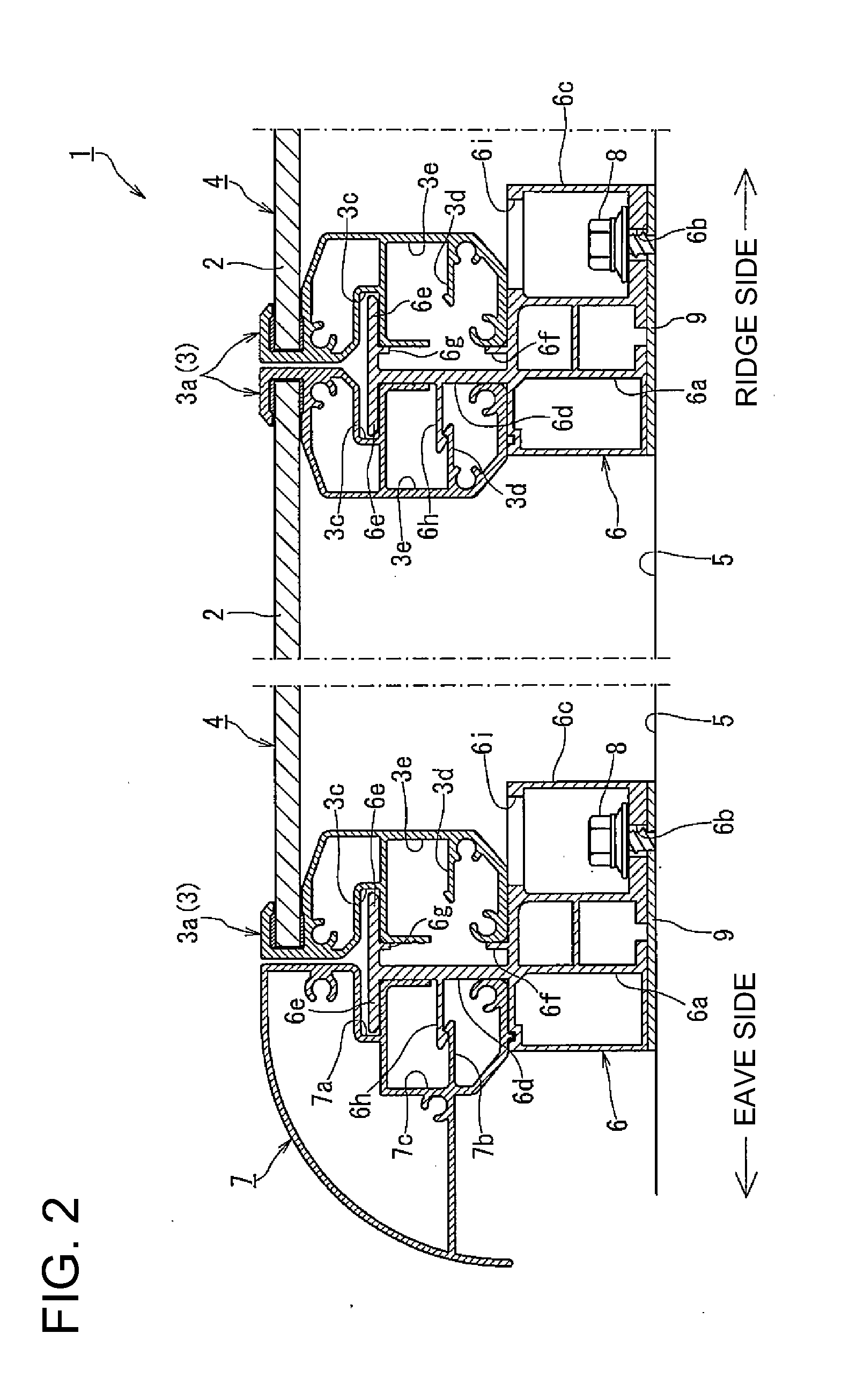
[0034]A connecting member for connecting ends of a plurality or photovoltaic cell modules and of decorative covers and the like in a photovoltaic power generation system installed on a roof according to one embodiment of the present invention is described in detail with reference to FIGS. 1 to 5. FIG. 1 is an entire perspective view of an example of the photovoltaic power generation system, which uses the connecting member according to one embodiment of the present invention, FIG. 2 is a side cross-sectional view illustrating a substantial part of the photovoltaic power generation system in FIG. 1, and FIG. 3 is an exploded perspective view illustrating the photovoltaic power generation system in FIG. 1 by exploding the same into substantial members. FIG. 4A is a perspective view illustrating an example in which the connecting member according to one embodiment of the present invention is used to connect the ends of the decorative covers in the photovoltaic power generation system i...


PUM


Abstract

There is provided a connecting member capable of eliminating displacement between ends, preventing a cost of installation from increasing and making the appearance of an installed photovoltaic cell module excellent only by being attached to the ends of predetermined members such as the photovoltaic cell module and a decorative cover.A connecting member 10 for connecting ends of adjacently arranged photovoltaic cell modules 4 fixed in a state in which the ends of the photovoltaic cell modules 4 each obtained by supporting an outer periphery of a photovoltaic cell panel 2 by frame bodies 3a and 3b are floating, including a plate-like upper piece 11, a plate-like lower piece 12 opposed to the upper piece 11 and a connecting piece 13 for connecting end sides on the same side of the lower piece 12 and the upper piece 11, the connecting member 10 capable of being fitted to the ends of the frame bodies 3a facing the same direction in the adjacent photovoltaic cell modules 4 so as to sandwich the same from a direction perpendicular thereto by the upper piece 11 and the lower piece 12.

Description

CROSS REFERENCE TO RELATED APPLICATIONS[0001]This application claims the benefit of priority to International Patent Application No. PCT / JP2009 / 062498 filed Jul. 9, 2009 claiming priority upon Japanese Patent Application No. 2009-100028 filed Apr. 16, 2009, of which full contents are incorporated herein by reference.BACKGROUND OF THE INVENTION[0002]1. Field of the Invention[0003]The present invention relates to a connecting member for connecting ends of predetermined members such as a photovoltaic cell module obtained by supporting an outer periphery of a photovoltaic cell panel by a frame body and a decorative cover arranged on an outer peripheral side of the photovoltaic cell module, and especially relates to the connecting member for connecting the ends of the predetermined members fixed in a state in which the ends thereof are floating.[0004]2. Description of the Related Art[0005]When installing the photovoltaic cell module obtained by supporting the outer periphery of the photo...

Claims


Application Information

Patent Timeline
Patent Type & Authority Applications(United States)
IPC IPC(8): H01R4/26
CPCF24J2/4636F24J2/5207F24J2/5211F24J2/5245F24J2/526H02S20/23F24J2002/4663F24J2002/5296Y02B10/12Y02E10/47F24J2/5262F24S25/61F24S2025/022F24S40/80F24S2025/6003F24S25/35F24S25/20F24S25/65F24S25/67Y02E10/50Y02B10/10
Inventor KOBAYASHI, SHUICHI
Owner YANEGIJUTSUKENKYUJO CO LTD
Why Eureka
Try Eureka