
Housing and display device provided with the housing

a display device and housing technology, applied in the direction of identification means, lighting and heating apparatus, instruments, etc., can solve the problems of insufficient strength of the entire liquid crystal display device, weak structural structure, easy deformation, etc., to enhance the strength of the display device, strengthen the structure, and enhance the assembling property

Active Publication Date: 2005-07-14
NEC LCD TECH CORP
View PDF6 Cites 14 Cited by
  • Summary
  • Abstract
  • Description
  • Claims
  • Application Information

AI Technical Summary

Benefits of technology

[0025] As explained above, the following advantageous effects can be given according to the housing and the display device provided with the housing of the present invention.
[0026] The first advantageous effect of the housing of the present invention is that the strength of the display device can be enhanced.
[0027] The reason is that the stepped structure comprised of the outer face section positioned at the outer side when combined and the inner face section positioned at the inner side when combined is formed on at least a part of the side face section of the frame member. Compared to the frame member wherein the side face is made of a single flat plate, this can realize a strong structure with respect to external force such as distortion. A remarkable effect can be obtained in particular in a thin-sized liquid crystal display device having a screen increased in size and a frame that is narrowed.
[0028] The second advantageous effect of the housing of the present invention is that the assembling property can be enhanced to thereby be capable of preventing the deterioration in display quality caused by the assembling failure.
[0029] The reason is that the corresponding outer face section and inner face section function respectively as a guide upon fitting the pair of frame members to each other, thereby being capable of maintaining parallelism of both frame members. This can prevent that both frame members are fitted as they are tilted to cause local stress. Further, this eliminates the displacement of the position or space of the components held inside.

Problems solved by technology

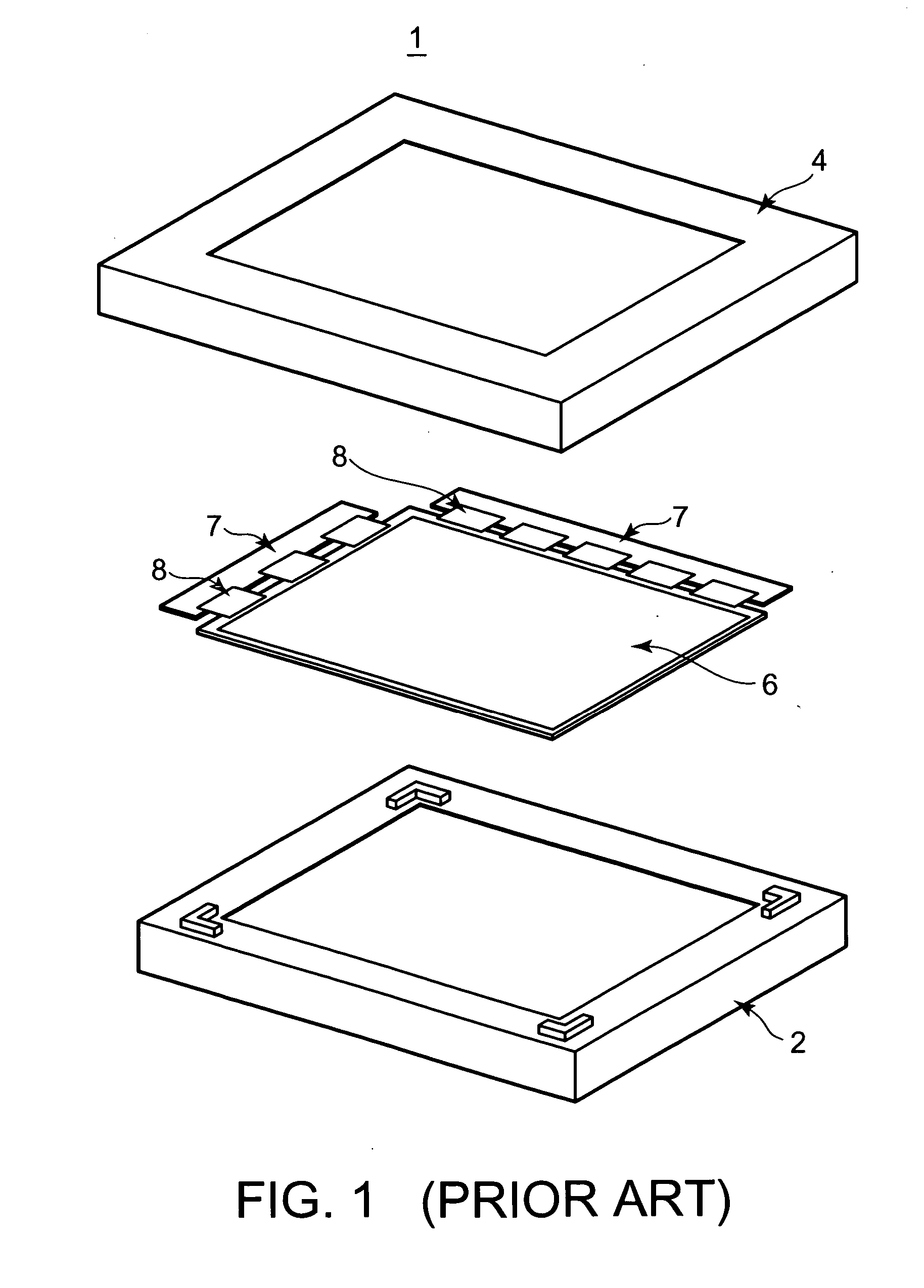
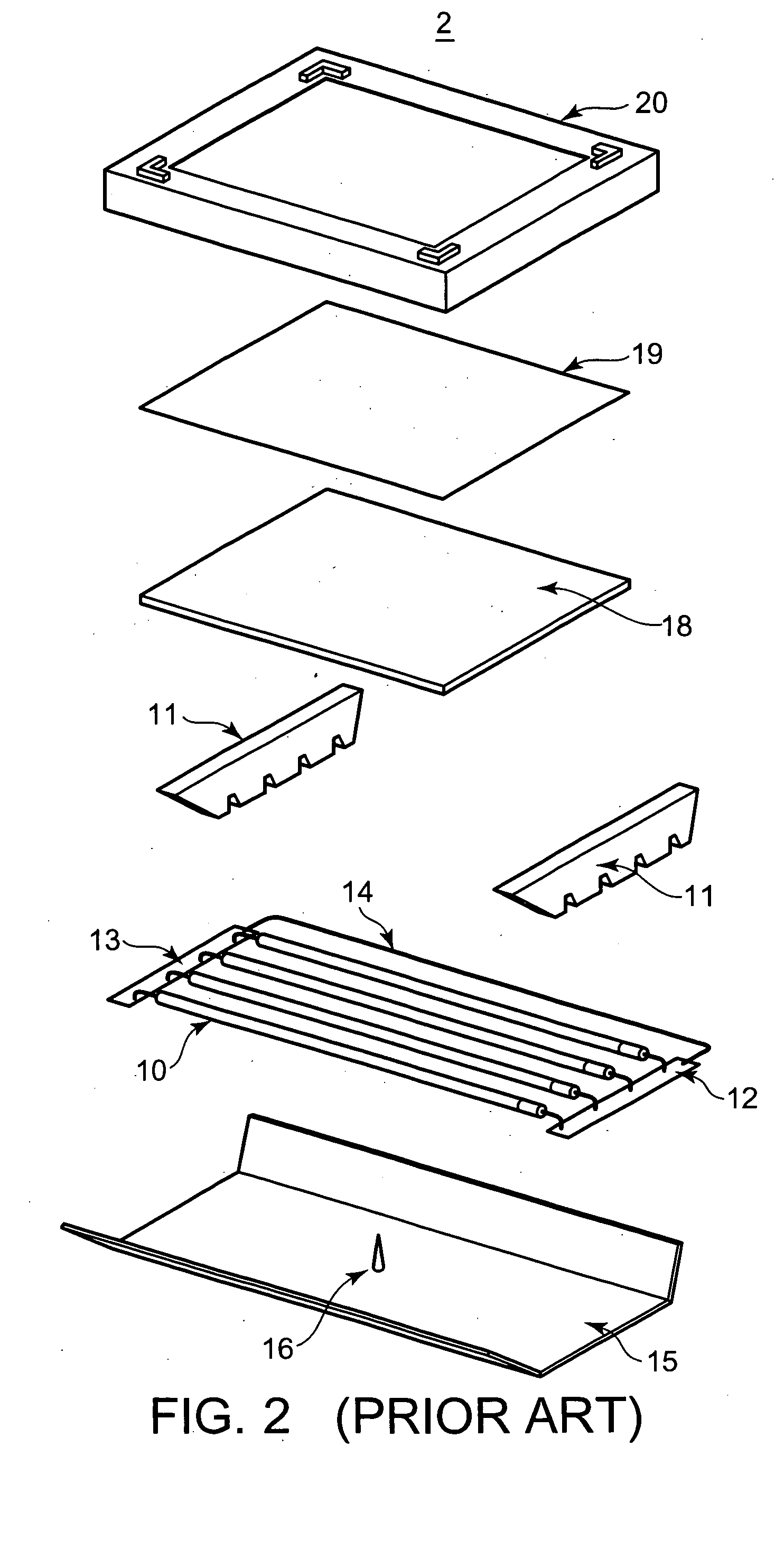
The first problem is that the strength of the entire liquid crystal display device 1 cannot sufficiently be maintained.
Consequently, it is structurally weak with respect to external force, thereby being easy to be deformed.
In particular, the width of the frame and the width of the side face are decreased as the screen size is increased and the size of the frame and thickness are decreased, thereby unable to assuredly hold each unit.
Moreover, the second problem is that the housing is difficult to be assembled, so that the deterioration in display quality caused by assembling failure is likely to occur.
Specifically, in the structure wherein a great-sized frame member is fitted to a small-sized frame member so as to cover the small-sized frame member, both frame members are prone to tilt during the fitting process, so that the assembling process requires practice.
Further, when the frame members are fitted as they are tilted, the position or space of each unit is shifted, resulting in deteriorating display quality.
This second problem appears more conspicuously with the increased screen size, narrowed frame and thinned size.
Additionally, the third problem is that, when frame members of plural types each having a different size are combined, frame members of plural types should separately be manufactured, thereby being unable to provide a reduction in cost.
Therefore, design cost or processing cost may be increased.
Further, in the structure wherein frame members of plural types are combined, these frame members should separately managed, thereby also increasing managing cost.
Moreover, the fourth problem is that, in the structure wherein frame members each having a different size are combined, a difference occurs in the appearance between the front and back, which makes the device bad-looking.
These problems occurs on not only a liquid crystal display device but also on a display device of any type at least holding a display panel by using a housing.

Method used


Image

  • Housing and display device provided with the housing
  • Housing and display device provided with the housing
  • Housing and display device provided with the housing

Examples


embodiments

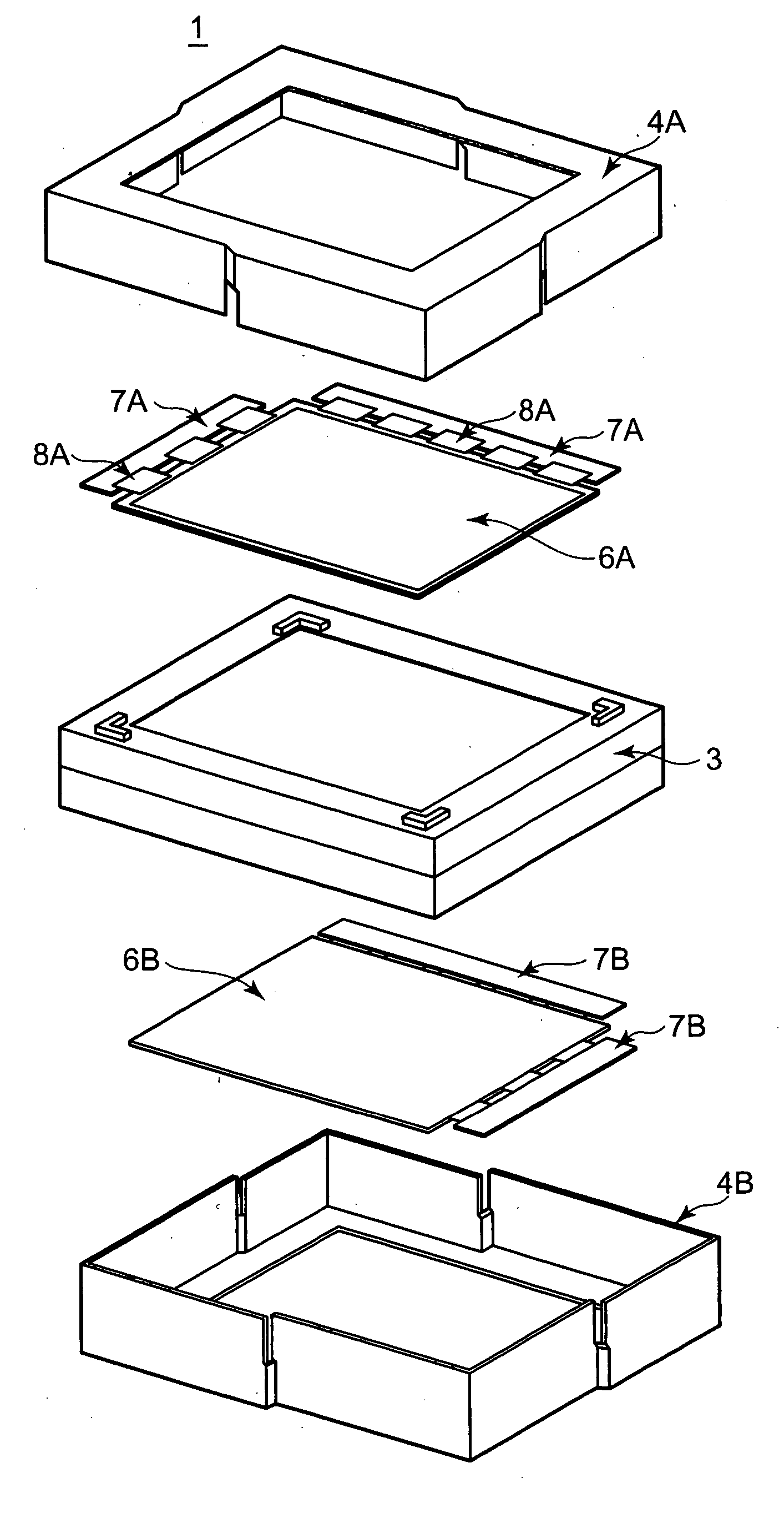
[0054] A housing structure and a double-sided liquid crystal display device provided with the housing according to one embodiment of the present invention will be explained with reference to FIGS. 5 to 17 in order to explain one embodiment of the present invention in more detail. FIG. 5 is an assembly drawing in which a double-sided liquid crystal display device is disassembled into each component, FIG. 6 is a perspective view showing a state wherein the housing according to the present invention is fitted, FIGS. 7A and 7B respectively show a top view and a right side view of FIG. 6, and FIG. 8 and FIG. 9 are sectional views. Further, FIGS. 10 to 17 are views showing a variation of the housing structure of the present invention. It should be noted that the present invention has a feature in the housing structure, so that a structure and shape of other components such as a liquid crystal display or backlight device held and fixed by the housing are not limited.

[0055] As shown in FIG...


PUM

PropertyMeasurementUnit
shapeaaaaaaaaaa
sizeaaaaaaaaaa
brightnessaaaaaaaaaa

Abstract

A housing for holding and fixing components of a liquid crystal display device is composed of a pair of frame members each having the same shape. Four sides of the side face of each frame member are formed such that an outer face section positioned at the outer side when combined and an inner face section positioned at the inner side when combined are stepped to each other, and a cut section is formed between the outer face section and the inner face section. The side face section of the frame member of the housing is formed to be stepped as described above, so that the strength and assembling property are enhanced, thereby being capable of preventing deterioration in display quality caused by the displacement of the position and space of the components.

Description

BACKGROUND OF THE INVENTION [0001] 1. Field of the Invention [0002] The present invention relates to a housing and a display device provided with the housing, and more particularly to a housing that is preferable for use in a display device having display face on both the front and back faces and a double-sided display device provided with the housing. [0003] 2. Description of the Prior Arts [0004] A flat-type display device such as a liquid crystal display device or plasma display panel or the like has spread as a display device, wherein its size has been increased. The following explanation is made by taking a liquid crystal display device as one representative example of such a flat-type display device. The liquid crystal display device has widely been used as a monitor for office automation equipment or television because of its feature of being compact, being thin-sized and providing reduced power consumption. The liquid crystal display device is classified into a directly-bene...

Claims


Application Information

Patent Timeline
Patent Type & Authority Applications(United States)
IPC IPC(8): G02F1/1333G02F1/13G02F1/13357G02F1/1347G09F9/00
CPCG02F1/133308G02F1/133608G02F2201/465G02F2001/133325G02F2001/133342G02F2001/13332G02F1/13332G02F1/133325G02F1/133342G02F1/1333
Inventor FUKUYOSHI, HIROKAZUONO, SHIN-ICHIROU
Owner NEC LCD TECH CORP
Learn More