Compression sleeve

Active Publication Date: 2011-03-24
CAREMED SUPPLY
View PDF21 Cites 46 Cited by
  • Summary
  • Abstract
  • Description
  • Claims
  • Application Information

AI Technical Summary

Benefits of technology

[0008]Thus, the compression sleeve could have multi-chamber-inflatable-like performance with less necessary fluid cond

Problems solved by technology

Additionally, blood stasis is a significant cause leading to the formation of thro

Method used


Image

  • Compression sleeve
  • Compression sleeve
  • Compression sleeve

Examples


Example

[0015]Reference will now be made in detail to the present preferred embodiments of the invention, examples of which are illustrated in the accompanying drawings. Wherever possible, the same reference numbers are used in the drawings and the description to refer to the same or like parts.

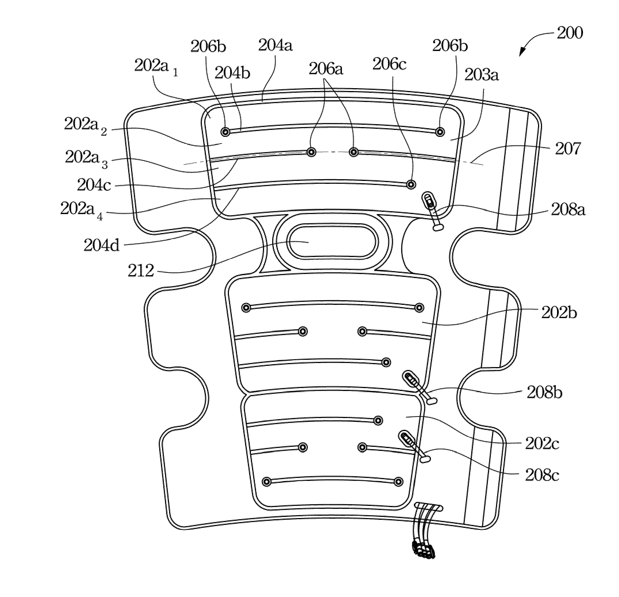
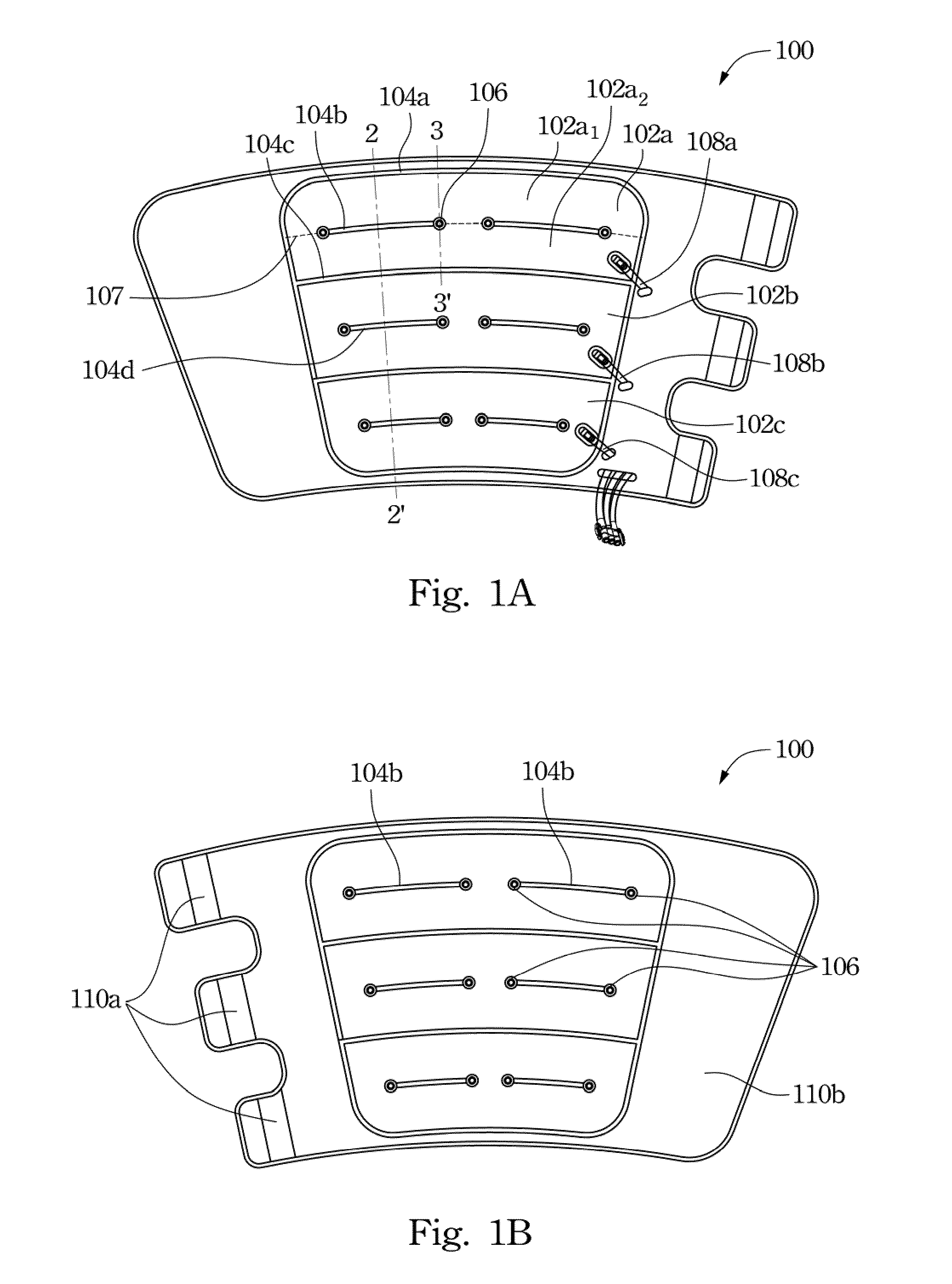
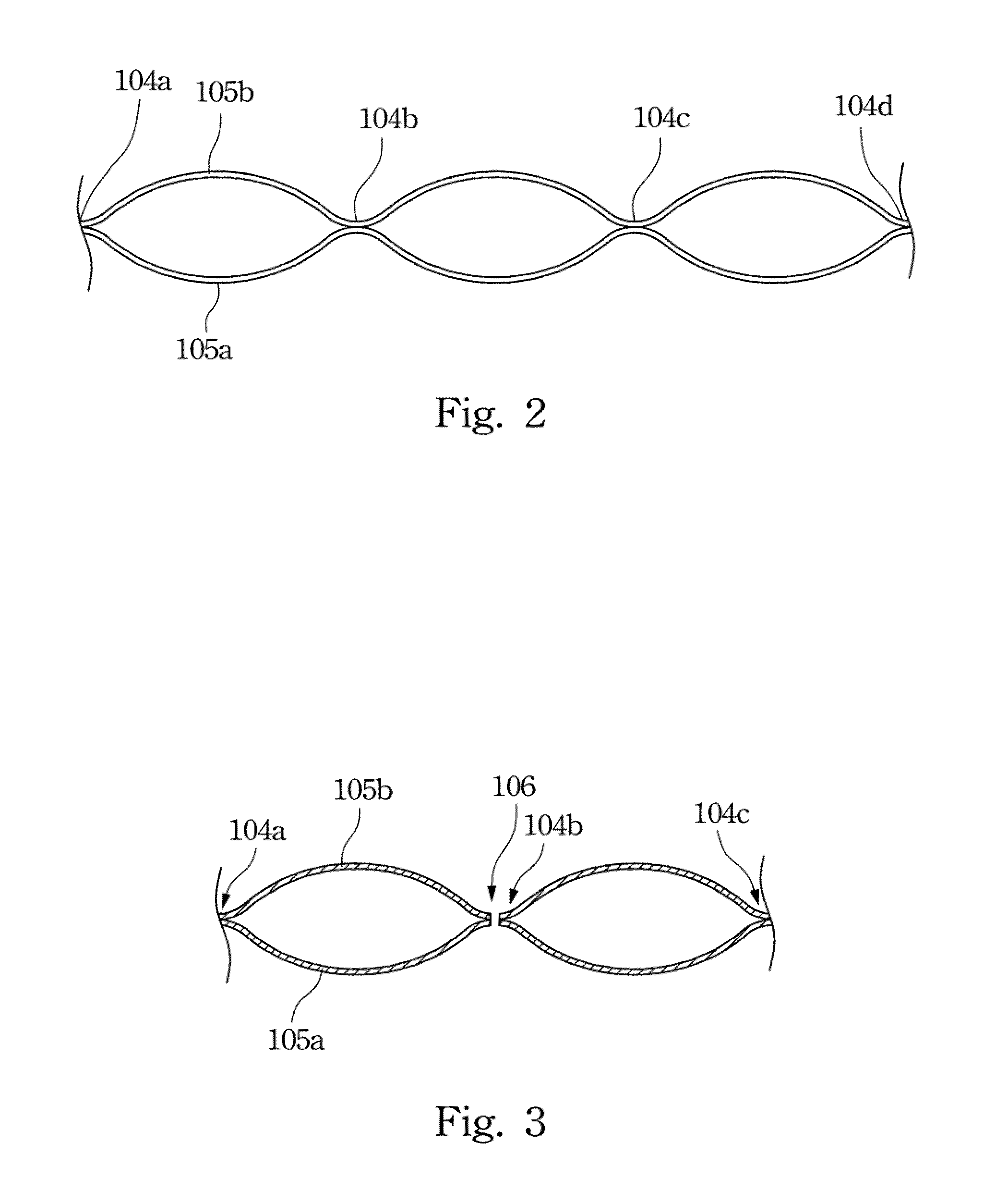
[0016]FIG. 1A and FIG. 1B respectively illustrate two opposite sides of a compression sleeve according to one embodiment of this invention. The compression sleeve 100 is to wrap around a patient's limb to apply repeating compression pulses so as to enhance the circulation in the limb. The compression sleeve 100 has three isolated inflatable sections or chambers (102a, 102b, 102c), which are respectively equipped with a conduit (108a, 108b, 108c) connected to a source of pressurized fluid (not illustrated in the drawings). Each isolated inflatable section (102a, 102b, 102c) is formed by and within a close-loop sealing contact, e.g. the sealing contact 104a plus the sealing contact 104c. In this embodi...


PUM


Abstract

A compression sleeve includes a first sheet, a second sheet, at least one close-loop sealing contact and at least two open-loop sealing contacts. The at least one close-loop sealing contact is formed between the first and second sheet so as to form an isolated inflatable section within the close-loop sealing contact. The at least two open-loop sealing contacts are disposed within the at least one close-loop sealing contact, wherein at least one of the at least two open-loop sealing contacts includes two through holes respectively at two opposite ends.

Description

BACKGROUND[0001]1. Field of Invention[0002]The present invention relates generally to a compression sleeve for use in a system for applying compressive forces or pressure to a patient's limb.[0003]2. Description of Related Art[0004]The velocity of blood flow in a patient's leg is known to decrease during confinement in bed. Such pooling or stasis of blood is particularly pronounced during surgery, immediately after surgery, and when the patient has been confined to bed for an extended period of time. Additionally, blood stasis is a significant cause leading to the formation of thrombi in the patient's leg, which may eventually cause serious injury or even death. Additionally, in certain patients, it is desirable to move fluid out of interstitial spaces in extremity tissues in order to reduce swelling associated with edema in the extremities. By enhancing the circulation in the limb, the arterial and venous blood flow could be improved.[0005]Intermittent pneumatic compression devices...

Claims


Application Information

Patent Timeline
IPC IPC(8): A61H7/00
CPCA61H9/0092A61H2201/165A61H2209/00A61H2205/108A61H2205/106
Inventor LIU, TSUNG-HSILIU, TSUNG-HSUAN
Owner CAREMED SUPPLY
Why Eureka
Try Eureka