Catheter retaining tool

a technology of retaining tool and catheter, which is applied in the field of catheter retaining tool, can solve the problems that the direction in which the operator can carry out the manipulation cannot be carried out, and achieve the effect of easy picking and easy operation

Active Publication Date: 2011-03-24
TERUMO KK
View PDF20 Cites 20 Cited by
  • Summary
  • Abstract
  • Description
  • Claims
  • Application Information

AI Technical Summary

Benefits of technology

[0008]It is an object of the present invention to provide a catheter indwelling device which can push out a guide wire stably and has high operability.

Problems solved by technology

Thus, adjustment of the location for manipulation or of the guide wire to a direction in which the operator can carry out the manipulation cannot be carried out.

Method used


Image

  • Catheter retaining tool
  • Catheter retaining tool
  • Catheter retaining tool

Examples


first embodiment

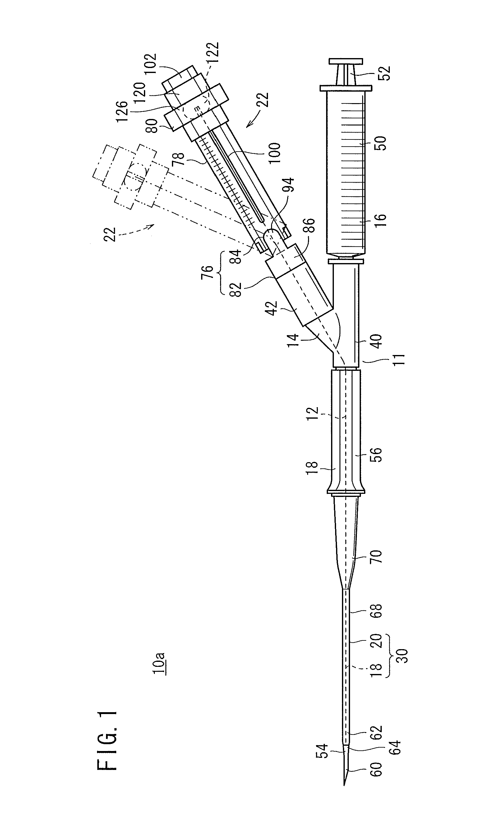
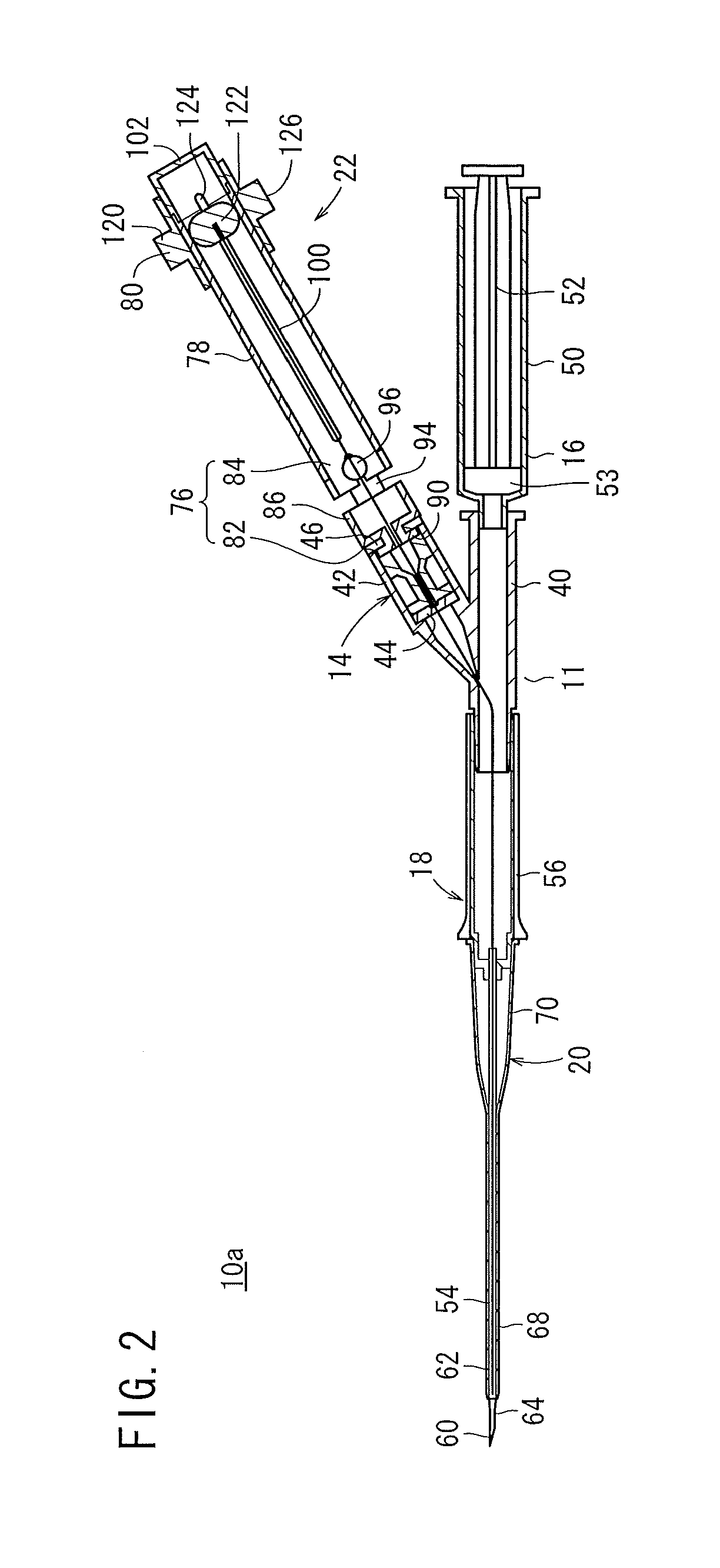
[0039]As shown in FIGS. 1, 2 and 3, a catheter indwelling device 10a has a puncture device 11 and a guide wire 12. The puncture device 11 has a Y hub (main body) 14, a syringe (blood accepting device) 16, an indwelling needle 30, and an operation means 22. The catheter indwelling device 10a should be housed in a predetermined case with the inside thereof sterilized. The Y hub 14 and the syringe 16 are transparent members so that the blood in the inside thereof can be confirmed.

[0040]The guide wire 12 is made of, for example, superelastic alloy or stainless steel and is approximately 15 cm. In an initial state, the guide wire 12 is inserted at a forward portion of approximately 10 cm thereof in the Y hub 14 and a puncture needle 18. A distal end portion of the guide wire 12 has particularly high flexibility and can be introduced readily into a blood vessel. Graduation symbols (not shown) each indicative of a length from the distal end are provided on the guide wire 12.

[0041]As shown...

second embodiment

[0082]Now, a catheter indwelling device 10b is described. Portions of the catheter indwelling device 10b (and 10c) that are identical to those of the catheter indwelling device 10a are denoted by the same reference numerals, and detailed description thereof is omitted.

[0083]As shown in FIG. 13, the catheter indwelling device 10b has a puncture device 11 and a guide wire 12. The puncture device 11 has a Y hub 14, a syringe 16, an indwelling needle 30 and an operation means 150. The operation means 150 corresponds to the operation means 22 described hereinabove and is provided on the puncture device 11 (side port 42).

[0084]The operation means 150 has a turning portion 152 for turning with respect to the side port 42, an extending portion 78 connected to the turning portion 152, and a slide portion 80 for pushing out the guide wire 12 along the extending portion 78.

[0085]The turning portion 152 corresponds to the turning portion 76 described hereinabove and has a first shank 82 which ...

third embodiment

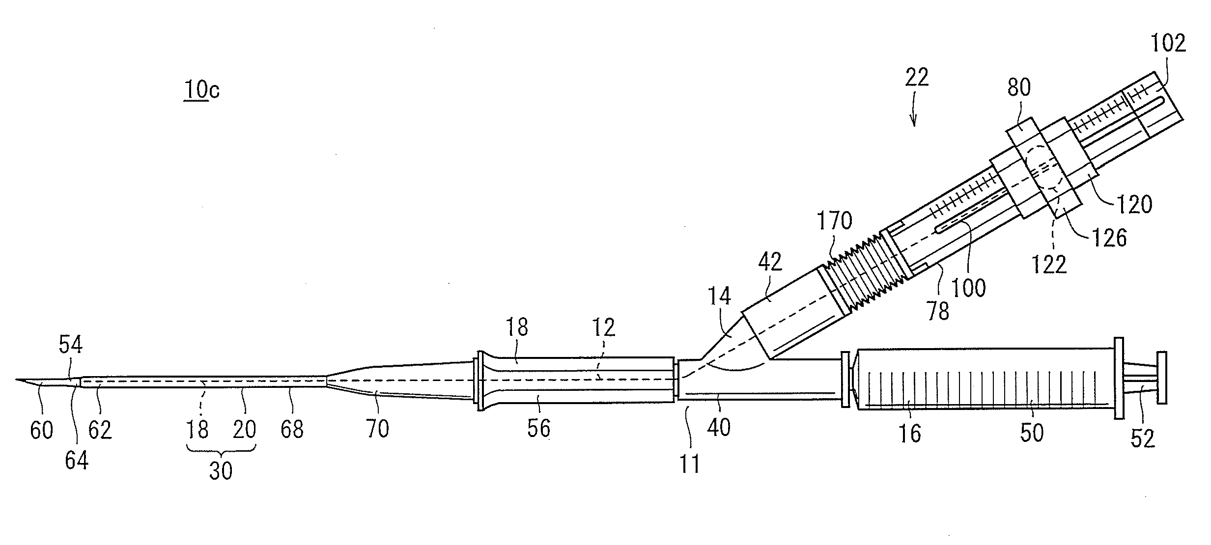
[0089]Now, a catheter indwelling device 10c is described.

[0090]As shown in FIG. 14, the catheter indwelling device 10c has a puncture device 11 and a guide wire 12. The puncture device 11 has a Y hub 14, a syringe 16, an indwelling needle 30 and a bellows tube 170. The bellows tube 170 corresponds to the operation means 22 and connects the puncture device 11 (side port 42) and the extending portion 78 to each other such that it acts as a pivoting portion for tilting the extending portion 78 to an optional direction.

[0091]The bellows tube 170 contracts in its initial states, and part of bellows 172 thereof are expanded in response to the tilting direction and the tilt amount in and with which the extending portion 78 is tilted. Consequently, as shown in FIG. 15, adjacent ones of the bellows 172 of the bellows tube 170 are kept in a parallel state (refer to a portion indicated by an arrow mark A) or a non-parallel state of a predetermined angle (refer to a portion indicated by an arr...


PUM


Abstract

A catheter retaining tool comprises a piercing tool, a guide wire and an operation device. The piercing tool includes a Y-hub, an outer needle, an indwelling needle and a syringe. The Y-hub includes a main port, an obliquely connected side port, and a hemostatic valve for keeping the side port liquid-tight. The guide wire is inserted by the operation device from the side port through the hemostatic valve into the outer needle. The operation device includes a turning portion made rotatable relative to the side port and having a hollow portion, an extending portion connected to the turning portion, and a slide portion for pushing out the guide wire along the extending portion. The turning portion includes a first rolling spindle and a second tilting spindle.

Description

TECHNICAL FIELD[0001]This invention relates to a catheter indwelling device (catheter retaining tool) for introducing a guide wire for guiding a catheter into a blood vessel.BACKGROUND ART[0002]When a patient is to be transfused, an indwelling needle is sometimes provided in a blood vessel (vein). Manipulation is carried out such that the indwelling needle punctures a blood vessel first and then blood is introduced into a syringe or the like from the puncture needle, whereafter a flashback is confirmed and then the puncture needle is removed while only a catheter is left in the blood vessel.[0003]In order to indwell the catheter certainly in the blood vessel, it is desirable to insert the catheter rather deeply in the blood vessel. To this end, after the indwelling needle punctures the blood vessel, a guide wire is fed out by a suitable amount from the puncture needle into the blood vessel, and then the puncture needle is pulled out with the guide wire left in the blood vessel. Ther...

Claims


Application Information

Patent Timeline
Patent Type & Authority Applications(United States)
IPC IPC(8): A61M25/00
CPCA61B5/1422A61B5/153A61M25/0606A61M2025/09125A61M25/09041A61M2025/028A61M25/0693A61B5/15003A61B5/150236A61B5/150244A61B5/150396A61B5/150503A61B5/1535
Inventor ASAI, TOSHIYA
Owner TERUMO KK
Why Eureka
Try Eureka