Intravascular implantable device having superior anchoring arrangement

a technology of implantable devices and implants, applied in the field of surgical devices, to achieve the effect of reducing the risk of thrombosis, reducing the risk of impact or trauma, and reducing the interference with the patient's muscular-skeletal anatomy

Inactive Publication Date: 2011-03-24
SYNECOR LLC
View PDF59 Cites 25 Cited by
  • Summary
  • Abstract
  • Description
  • Claims
  • Application Information

AI Technical Summary

Benefits of technology

[0010]Unlike the previous approaches to anchoring intravascular implantable devices near the middle of the patient's torso, embodiments of the present invention anchor the body portion of the intravascular implantable device in a vein that is located superior to the heart and still generally within the torso, such as the right or left cephalic veins, the right or left innominate (brachiocephalic) veins or the right or left subclavian veins. In conducting investigations with the previous approach of anchoring in the middle of the device in the thorax, the inventors of the present invention discovered that the previous anchoring arrangement generally moved in synchrony with respiration, rubbing the anchor and the intravascular implantable device against the vascular walls of the inferior vena cava and thereby causing unwanted irritation, thrombosis and / or fibrosis. Anchoring in the middle of the device also tended to constrain the movement of the device within the inferior vena cava and created more locations along the vessel for unwanted irritation, thrombosis and / or fibrosis.
[0012]In one embodiment, the tether portion of the implantable device extends across the sub-clavicle crush zone and the anchor is located peripheral of the sub-clavicle crush zone. The distal portion of the body of the device is proximate, but generally does not extend into, the subclavian crush zone. In this way, the anchor is located superior to the heart and in a manner so as to minimize interference with the patient's muscular-skeletal anatomy.
[0013]In one embodiment, the present invention solves the problems of previously utilized anchor locations by providing a tether portion at a distal portion of the body of the implantable device. In one embodiment, the tether portion is anchored into the vasculature superior to the heart with a conventional stent. In one embodiment, the vascular anchor is preferably separate from the implantable device and captures a tether portion that extends from the implantable device between the anchor and the vasculature. Alternatively, the anchor may be incorporated as part of the implantable device. In one embodiment, the vascular anchor and / or the tether portion of the implantable device include mechanisms to optimize interference between the anchor and the tether portion in a manner that does not induce a rupture of the vessel while providing for adequate clinical attachment of the implantable device within the patient.
[0014]In one embodiment, the anchoring of the present invention at the distal portion of the body of the intravascular implantable device permits the main body portion and proximal body portions of the device to more effectively float in the bloodstream, thereby reducing the risk of thrombosis for those portions, as well as reducing the risk of impact or trauma on the vessel walls. It is theorized that the reduction in the risk of thrombosis may be at least partly due to the more intermittent and random nature of the interaction of these portions of the body of the device with the vessel walls which reduces the indwelling time required for effective fibrosis of the device against the vessel wall, and also tends to reduce the size of any thrombosis formed on the device. With respect to thrombosis and fibrosis at the distal portion of the device, the present invention takes advantage of the fact that stenosis of the cephalic vein, the innominate vein or the subclavian vein is less critical than stenosis of many other veins and that closure or loss of those veins is not life threatening.
[0015]In another embodiment, the anchoring of the intravascular implantable device superior to the heart in accordance with the present invention, such as in the pectoral region, for example, provides for easier bailout in the event of a problem with the device requiring explantation or in the event that the device is to be removed and replaced with, for example, a conventional can-based device.

Problems solved by technology

Anchoring in the middle of the device also tended to constrain the movement of the device within the inferior vena cava and created more locations along the vessel for unwanted irritation, thrombosis and / or fibrosis.

Method used


Image

  • Intravascular implantable device having superior anchoring arrangement
  • Intravascular implantable device having superior anchoring arrangement
  • Intravascular implantable device having superior anchoring arrangement

Examples


Embodiment Construction

[0042]In the following detailed description of the present invention, numerous specific details are set forth in order to provide a thorough understanding of the present invention. However, one skilled in the art will recognize that the present invention may be practiced without these specific details. In other instances, well-known methods, procedures, and components have not been described in detail so as to not unnecessarily obscure aspects of the present invention.

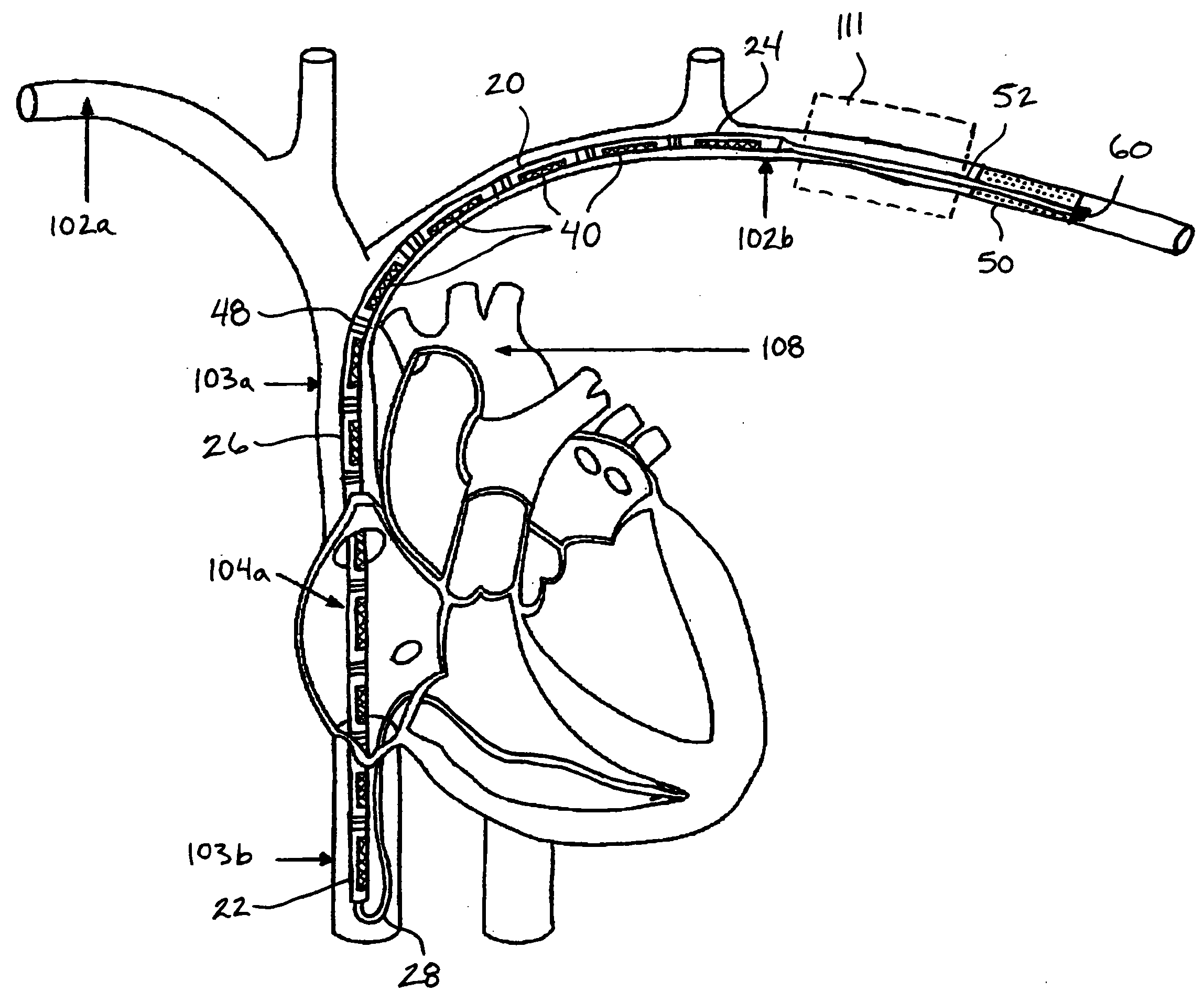
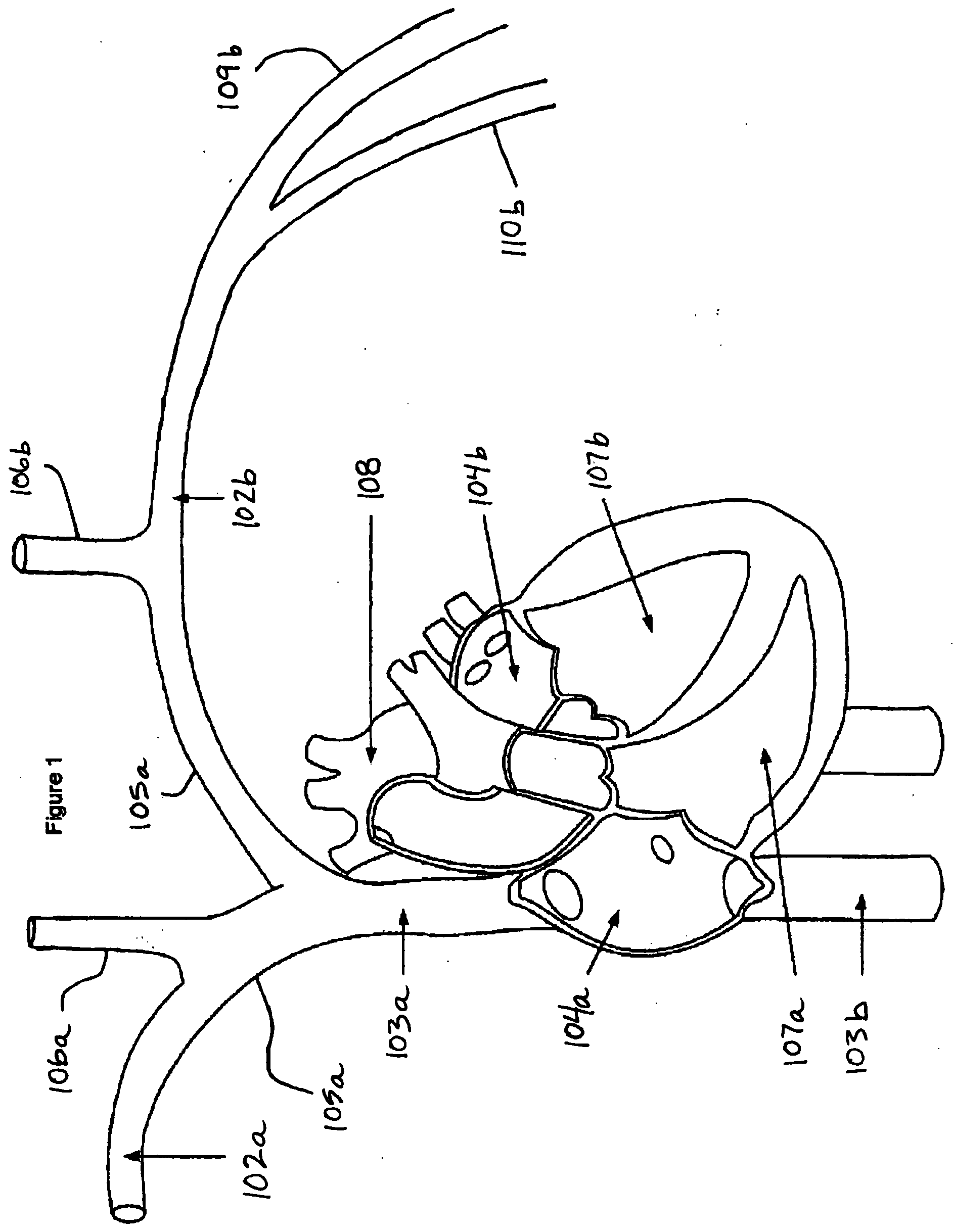
[0043]Referring now to FIG. 1, the general cardiac anatomy of a human is depicted, including the heart and major vessels. The following anatomic locations are shown and identified by the listed reference numerals: Right Subclavian 102a, Left Subclavian 102b, Superior Vena Cava (SVC) 103a, Inferior Vena Cava (IVC) 103b, Right Atrium (RA) 104a, Left Atrium (LA) 104b, Right Innominate / Brachiocephalic Vein 105a, Left Innominate / Brachiocephalic Vein 105b, Right Internal Jugular Vein 106a, Left Internal Jugular Vein 106b, Ri...


PUM


Abstract

Methods, systems and devices are provided for anchoring an intravascular implantable device within a vessel that is located superior to the heart, i.e. above the heart in a direction toward the head of a patient. Also provided is a method of providing an intravascular device and instructions for implanting the intravascular device, comprising providing an intravascular device having an elongate device body with a proximal end and a distal end that is adapted for chronic implantation within the vasculature of a patient and that includes a distal portion of the intravascular device proximate the distal end of the elongate device body, and providing instructions for chronically implanting the intravascular device substantially wholly within the vasculature of a patient in a target vessel superior to the heart of the patient.

Description

RELATED APPLICATIONS[0001]This application is a continuation of application Ser. No. 11 / 999,519 filed Dec. 4, 2007, which claims the benefit of U.S. Provisional Application No. 60 / 868,434 filed Dec. 4, 2006, and claims the benefit of U.S. Provisional Application No. 60 / 868,437, filed Dec. 4, 2006, and U.S. Provisional Application No. 61 / 005,354, filed Dec. 3, 2007, the disclosures of which are hereby incorporated by reference in their entireties.FIELD OF THE INVENTION[0002]The present invention relates generally to surgical devices and methods for retaining medical devices within the body, and more specifically to a method and system for anchoring an intravascular implantable device within a vessel that is located superior to the heart.BACKGROUND OF THE INVENTION[0003]Implantable medical devices such as pacemakers, defibrillators, and implantable cardioverter defibrillators (“ICDs”) have been successfully implanted in patients for years for treatment of heart rhythm conditions. Pace...

Claims


Application Information

Patent Timeline
Patent Type & Authority Applications(United States)
IPC IPC(8): A61N1/362A61N1/39
CPCA61N1/057A61F2/95
Inventor RANSBURY, TERRANCEHOLBROOK, KEVIN
Owner SYNECOR LLC
Why Eureka
Try Eureka