Stent With Constant Stiffness Along the Length of the Stent

Active Publication Date: 2011-03-24
MEDTRONIC VASCULAR INC
View PDF97 Cites 14 Cited by
  • Summary
  • Abstract
  • Description
  • Claims
  • Application Information

AI Technical Summary

Benefits of technology

[0008]It is an aspect of the present invention to provide a stent that has substantially constant stiffness along the length

Problems solved by technology

When tracking stents on a delivery system in the lumen to a deployment site, if the stiffness of the stent varies along the length of the stent, an increase in end flaring an

Method used


Image

  • Stent With Constant Stiffness Along the Length of the Stent
  • Stent With Constant Stiffness Along the Length of the Stent
  • Stent With Constant Stiffness Along the Length of the Stent

Examples


Embodiment Construction

[0025]The following detailed description is merely exemplary in nature and is not intended to limit the invention or the application and use of the invention. Furthermore, there is no intention to be bound by any expressed or implied theory presented in the preceding technical field, background, brief summary or the following detailed description.

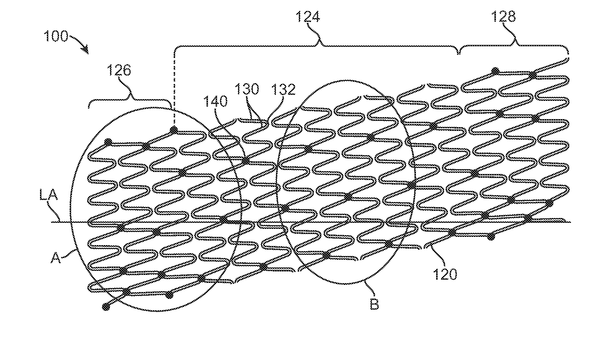
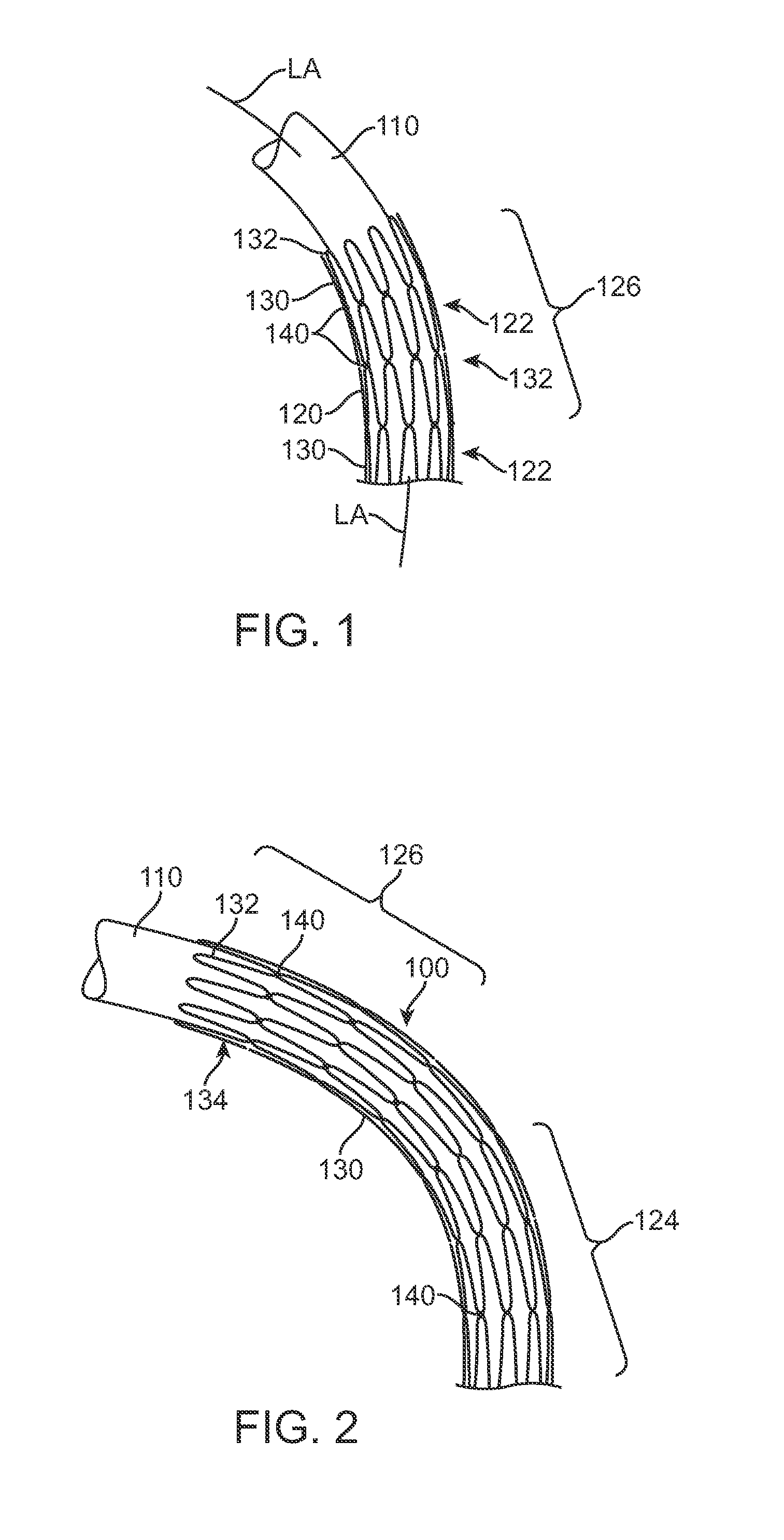
[0026]FIG. 1 schematically illustrates a portion of a stent 100 that is crimped onto a delivery system 110 and is being tracked to a target deployment site. Only one end portion 126 of the stent 100 is illustrated in FIG. 1. As illustrated, the stent 100 includes a wave form 120 that includes a plurality of struts 130 and a plurality of crowns 132. Each crown 132 connects two adjacent struts 130. The wave form 120 is wrapped around a longitudinal axis LA of the stent 100, to define a plurality of turns 122, The longitudinal axis LA of the stent 100 is illustrated in FIG. 1 as being curved, due to the bending of the delivery system 110 and t...


PUM

PropertyMeasurementUnit
Angleaaaaaaaaaa
Lengthaaaaaaaaaa
Angleaaaaaaaaaa

Abstract

A stent includes a wave form that includes a plurality of struts and a plurality of crowns. Each crown connects two adjacent struts within the wave form. The wave form is wrapped around a longitudinal axis at a pitch angle to define a plurality of turns and has a central portion and two end portions located on opposite sides of the central portion. At least some of the struts located in the end portions have lengths longer than an average length of all of the struts of the wave form. The stent also includes a plurality of connections. Each connection connects selected crowns from adjacent turns. The connections are positioned along the stent substantially equally so that a density of the number of connections of the end portions is substantially equal to a density of the number of connections of the central portion.

Description

CROSS-REFERENCE TO RELATED APPLICATIONS[0001]This application claims the benefit of priority from U.S. Provisional Patent Application Ser. No. 61 / 243,581, filed on Sep. 18, 2009, the entire content of which is incorporated herein by reference. This application also claims the benefit of priority from U.S. Provisional Patent Application Ser. No. 61 / 243,578, 61 / 243,582, 61 / 243,592, 61 / 243,597, and 61 / 243,600, all filed on Sep. 18, 2009, the entire contents of all of which are incorporated herein by reference.BACKGROUND OF THE INVENTION[0002]1. Field of the Invention[0003]The present invention is generally related to a stent having a constant stiffness along the length of the stent, and a method for manufacturing a stent having a constant stiffness along the length of the stent.[0004]2. Background of the Invention[0005]A stent is typically a hollow, generally cylindrical device that is deployed in a body lumen from a radially contracted configuration into a radially expanded configurat...

Claims


Application Information

Patent Timeline
IPC IPC(8): A61F2/82B31F1/00
CPCA61F2/88A61F2/915Y10T29/49826A61F2002/91525A61F2002/91558A61F2002/91508B23K2101/22B21F1/04B21F3/02B21F45/008B23K31/027
Inventor BLISS, RICHARDGOSHGARIAN, JUSTINLAM, RUI
Owner MEDTRONIC VASCULAR INC
Why Eureka
Try Eureka