
Voice-quality evaluating system, communication system, test management apparatus, and test communication apparatus

a voice quality and evaluation system technology, applied in the field of voice quality evaluation system, communication system, test management apparatus, test communication apparatus, can solve problems such as deterioration in security, increase in work procedures, and inability to allow control information for voice quality testing to be transmitted and received by packets according to a different protocol than rtp such as tcp

Inactive Publication Date: 2011-03-24
FUJITSU LTD
View PDF9 Cites 6 Cited by
  • Summary
  • Abstract
  • Description
  • Claims
  • Application Information

AI Technical Summary

Benefits of technology

Enables voice quality testing without modifying network settings, improving security by allowing control information to pass through firewalls, thus simplifying the testing process and maintaining network integrity.

Problems solved by technology

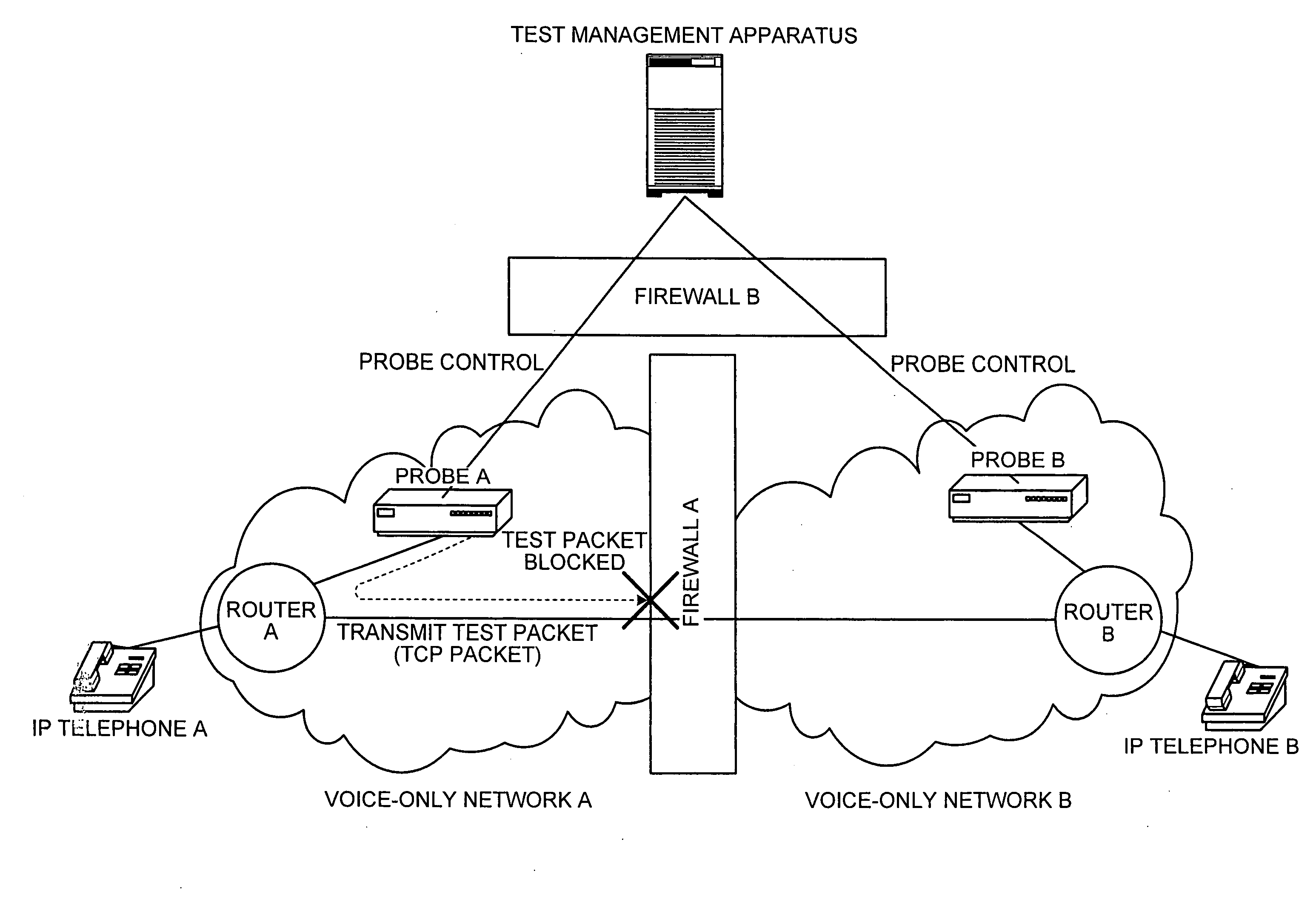
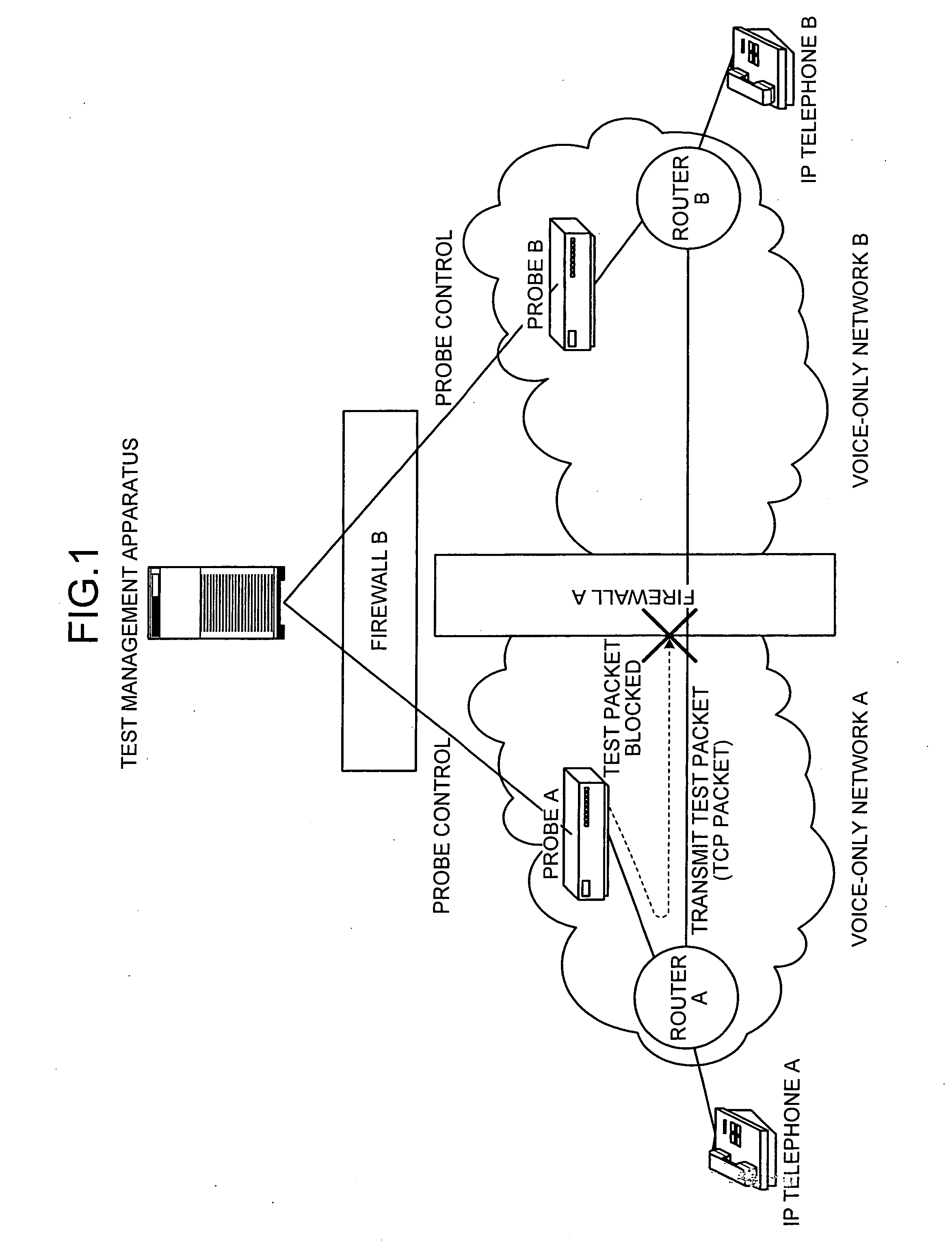
However, in the conventional technology disclosed in Japanese Patent Application Laid-Open No. 2004-297803, in a voice communication system in recent years in which a network is set to allow only a real-time transport protocol (RTP) packet to pass on a transmission path based on a security policy, it is impossible to allow control information for voice quality testing transmitted and received by packets according to a protocol different from the RTP such as a transmission control protocol (TCP) to pass.
This not only causes an increase in work procedures but also cause a problem of deterioration in security.
The burden of cost involved in this change poses a problem.
Therefore, even if the conventional technologies are combined, it is impossible to exclude connection from terminal apparatuses, which are not permitted to make connection, without changing specifications of the conventional apparatuses and networks and perform voice quality testing without changing a structures and setting of a network of a voice communication system.

Method used


Image

  • Voice-quality evaluating system, communication system, test management apparatus, and test communication apparatus
  • Voice-quality evaluating system, communication system, test management apparatus, and test communication apparatus
  • Voice-quality evaluating system, communication system, test management apparatus, and test communication apparatus

Examples


first embodiment

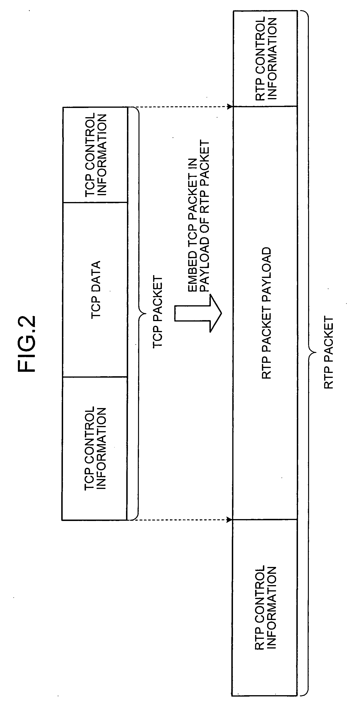
[0059]Although FIG. 2 is a schematic for explaining the overview of the RTP-packetization of the TCP packet performed according to the present invention, only the TCP data may be embedded in the payload of the RTP packet without adding the TCP control information.

[0060]FIG. 3 is a schematic for illustrating a method of using the RTP packet generated by the RTP-packetization of the TCP packet: (a) is a diagram of how to use the RTP packet in an ordinary case; and (b) is a diagram of how to use the RTP packet according to the present invention.

[0061]As shown in (a) of FIG. 3, usually, a voice input subjected to digital conversion by an A / D converter and encoded is RTP-packetized. When this RTP packet is received via a network, the RTP packet is RTP-depacketized according to a procedure opposite to that of the RTP-packetization. This depacketized packet is decoded, subjected to analog conversion by a D / A converter, and output.

[0062]On the other hand, as shown in (b) of FIG. 3, accordin...

second embodiment

[0116]FIG. 13 is a sequence diagram of the test suspension processing between the test management apparatus 100 and the probe A 200 according to the The probe A 200 is set as a test-packet transmission side probe. As shown in the figure, a test suspension instruction is input from the terminal apparatus 900 (step S191). The test-suspension-processing unit 101g detects the test suspension instruction received via the terminal-apparatus I / F unit 107 of the test management apparatus 100 (step S192).

[0117]The SIP-URI reception-permission-judgment processing unit 101b determines a test-packet transmission side probe based on a test scenario (step S193). The SIP-URI reception-permission-judgment processing unit 101b requests the SIP server 300 that the session-start-request processing unit 101c start a session with the transmission side probe (steps S194 and S195). In response to this request, the SIP server 300 transmits the request to the probe A 200 (step S196) and notifies the test m...

third embodiment

[0132]FIG. 17 a sequence diagram of the test resumption processing between the test management apparatus 100 and the probe A 200 according to the The probe A 200 is set as a test-packet transmission side probe. As shown in the figure, first, a test resumption instruction is input from the terminal apparatus 900 (step S231). The test-resumption processing unit 101h detects the test resumption instruction received via the terminal-apparatus I / F unit 107 of the test management apparatus 100 (step S232).

[0133]The SIP-URI reception-permission-judgment processing unit 101b determines a test-packet transmission side probe based on a test scenario (step S233) and requests the SIP server 300 that the session-start-request processing unit 101c start a session with the transmission side probe (steps S234 and S235). In response to this request, the SIP server 300 transmits the request to the probe A 200 (step S236) and notifies the test management apparatus 100 that the request is received (st...


PUM


Abstract

A voice-quality evaluating system, in a secure network that allows a voice packet to pass, transmits and receives communication information for a voice quality testing between a test management apparatus and a test communication apparatus connected to the network and between the test communication apparatuses, for the voice quality testing between the test communication apparatuses arranged on the network. The voice-quality evaluating system embeds the communication information in a payload of the voice packet, and transmits and receives communication-information-embedded voice packet.

Description

CROSS-REFERENCE TO RELATED APPLICATION(S)[0001]This application is related to and is a continuation of U.S. Ser. No. 11 / 495,692 filed on Jul. 31, 2006 and claims priority to Japanese Patent Application No. 2006-083943, filed on Mar. 24, 2006, incorporated herein by reference.BACKGROUND[0002]1. Field[0003]The present invention relates to a technology for transmitting and receiving voice information for voice-quality test between a test management apparatus and a test communication apparatus and between test communication apparatuses in a network for transmitting and receiving voice packets to perform a voice-call communication.[0004]2. Description of the Related Art[0005]In recent years, a voice communication system using the Internet has been widespread. In such a voice communication system, since it is possible to build the system at relatively low cost, it is possible to provide a voice communication service inexpensively.[0006]It is necessary to perform various tests to measure a...

Claims


Application Information

Patent Timeline
Patent Type & Authority Applications(United States)
IPC IPC(8): G10L11/00
CPCH04L12/2697H04L65/80H04L43/50H04L29/06027H04L65/1104H04L65/1101
Inventor KIMURA, NOBUKOMIZUTA, KAZUOTAKEBAYASHI, KENNISHIDA, HIROSHI
Owner FUJITSU LTD
Learn More