Locking Safety Mechanism for Suspended Transport Apparatus

a safety mechanism and transport apparatus technology, applied in the field of hoisting devices, can solve problems such as possible catastrophic situation, suspended patients, and cataclysmic event, and achieve the effect of improving safety in suspended transport apparatuses

Active Publication Date: 2011-03-31
IMHOFF KARL
View PDF28 Cites 16 Cited by
  • Summary
  • Abstract
  • Description
  • Claims
  • Application Information

AI Technical Summary

Benefits of technology

[0037]In the embodiments with the gripping member positioned to engage a top surface of the rail, the presence of the reinforcing member provides greater degree of the rail engagement to stop the carriage on the track. Such increased engagement is due to sandwiching of the rail between the reinforcing member and the locking-device gripping member.
[0038]It should be understood that, while the present invention is primarily concerned with improving safety in suspended carrier apparatuses for transporting temporarily or permanently disabled persons such as hoisting devices for lifting patients or in residential setting, this invention may also be used with a wide variety of suspended transport apparatuses in many applications. Such applications may include industrial assembly lines such as in automotive manufacturing. This invention may also find its use in other suspended transport systems like funiculars or a variety of rail-utilizing attraction devices.

Problems solved by technology

This may result in a potentially catastrophic event for a suspended patient supported by the patient-lift device dropping the patient and having the unit fall on top of either the patient or an assistant or both.
In the earlier versions of the patient-lift devices secured to a single overhead track with bumper end-stops at the track ends, the bumper end-stops are bolted in a sandwich fashion which has been recognized as insufficient.
However, any such attachment is removable and, if not present, could cause the same possible catastrophic situation.
Therefore, if a failure occurs, the perpendicular track along with the patient-lift device may fall off the failed end of the side track resulting in the same unfortunate situation as above.

Method used


Image

  • Locking Safety Mechanism for Suspended Transport Apparatus
  • Locking Safety Mechanism for Suspended Transport Apparatus
  • Locking Safety Mechanism for Suspended Transport Apparatus

Examples


Embodiment Construction

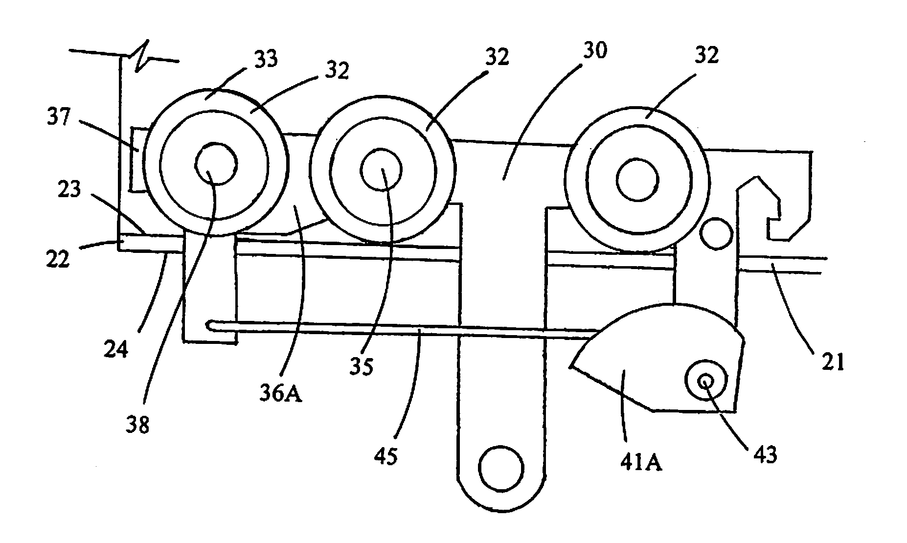
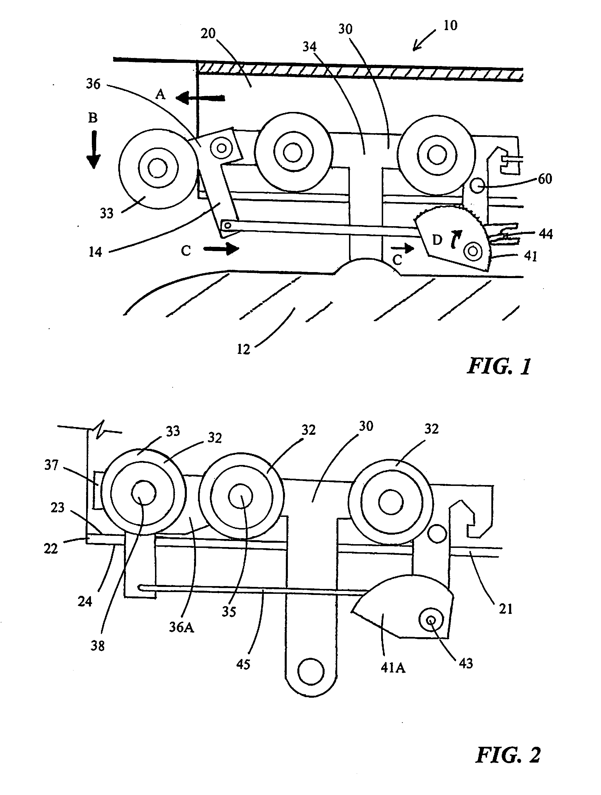
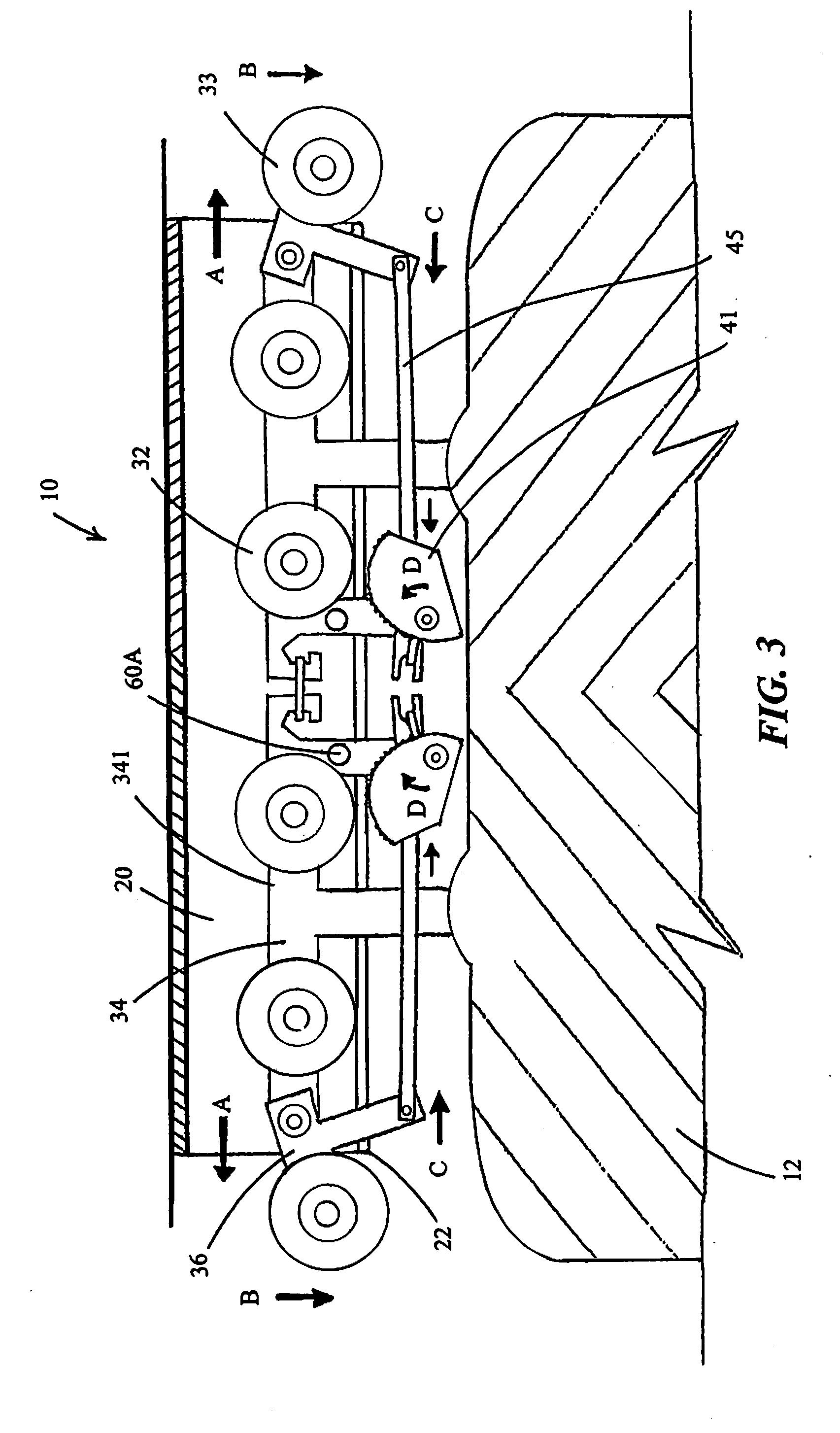
[0050]The FIGURES illustrate the improvement in suspended patient-carrier / transport apparatus 10 which includes an overhead rail 20 forming a horizontal track 21 which terminates at a track-end 22. FIGS. 1 and 2 best show a carrier device 12 supported by a carriage 30 having a plurality of aligned rollers 32 rideable along horizontal track 21. Suspended patient-carrier / transport apparatus 10 includes a locking safety mechanism 14 which prevents carriage 30 from running off track 21 through a recognition of track-end 22.

[0051]FIGS. 1-5 show locking safety mechanism 14 as including carriage 30 having a main carriage portion 34 which is movable along track 21 and a forward carriage portion 36 vertically movable with respect to main portion 34. FIG. 1, 3 show forward carriage portion 36 pivotably secured with respect to main portion 34. At least one of the aligned rollers 32 is a front roller 33 secured to forward carriage portion 36. FIG. 1 best illustrates that when front roller 33 ru...


PUM


Abstract

A suspended patient-carrier/transport apparatus of the type including an overhead rail forming a horizontal track terminating at a track-end, and a carrier device supported by a carriage having a plurality of aligned rollers rideable along the track. The inventive suspended transport apparatus has a locking safety mechanism including the carriage having a main carriage portion and a forward carriage portion. A track-end detector is at the forward carriage portion and movably secured with respect thereto such that the track-end detector moves downwardly when it runs beyond the track-end. A locking device is operatively connected with respect to the track-end detector such that downward movement thereof causes the locking device to engage the rail thereby stopping the carriage on the track.

Description

FIELD OF THE INVENTION[0001]The present invention relates to hoisting devices for handling patients. More specifically, to rail-suspended patient-handling devices and safety features for such device.BACKGROUND OF THE INVENTION[0002]The industry of patient lifts has grown exponentially over the past few years. Initially, such devices were primarily located in homes of disabled people. Presently, patient lifts are placed in hospital rooms, physical therapy centers, senior centers and other similar facilities nationwide. Along with the growth of the patient-lift industry, much improvements have been made to the patient-lift devices themselves to better serve needs of disabled individuals and their care givers.[0003]The evolution of patient lifts went through a number of stages. The earliest patient lifts are secured to a single overhead track with bumper end-stops at the end of the track. Such single track runs from a position over a bed to a bathroom. These early patient lifts are eit...

Claims


Application Information

Patent Timeline
Patent Type & Authority Applications(United States)
IPC IPC(8): A61G7/10B61B3/00B61H7/12
CPCA61G7/1042B61B3/00B60T1/14A61G7/1063B66C9/18B66C11/00A61G7/1034
Inventor IMHOFF, KARL
Owner IMHOFF KARL
Why Eureka
Try Eureka