Flow channel switching device

a technology of flow channel and switching device, which is applied in the direction of water supply installation, couplings, transportation and packaging, etc., can solve the problems of reducing the operation rate of the device, reducing the pressure loss of the high-pressure fluid and water hammer phenomenon, and preventing the pressure loss of the high-pressure fluid and water hammer

Inactive Publication Date: 2011-03-31
KK TOSHIBA
View PDF12 Cites 1 Cited by
  • Summary
  • Abstract
  • Description
  • Claims
  • Application Information

AI Technical Summary

Benefits of technology

[0012]Since in the embodiment, the first and second actuators are controlled to independently operate so as to alternately open and close the first and second holes of the high-pressure chamber using the first and second valve bodies, pressure loss of the high-pressure fluid and water hammer phenomenon can be prevented. As a result, flow channels for the high-pressure fluid can be switched smoothly.

Problems solved by technology

However, in the switch valve disclosed in Patent Document 1, since the flow channels are opened and closed by sliding the spool along the inner peripheral wall of the valve chamber, it is difficult to completely close the flow channels if a fluid of an extremely high pressure is handled as in a seawater desalting plant.
Namely, if this switch valve is used in the seawater desalting plant, leakage of seawater may well occur.
This reduces the operation rate of the device.
To compensate for this disadvantage, if a pair of devices is connected to a single reverse osmotic film tank and is operated alternately, the entire system will be enlarged and its equipment cost will inevitably increase.
In addition, in the switch valve of Patent Document 1, since a plurality of flow channels are simultaneously opened and closed by moving the spool, the flow channels cannot be opened or closed at different times. Accordingly, the switching time of each flow channel cannot be finely adjusted in accordance with, for example, the pressure difference between the flows of the to-be-contracted liquid in the channels.
Therefore, the flow channels cannot be smoothly switched.

Method used


Image

  • Flow channel switching device
  • Flow channel switching device
  • Flow channel switching device

Examples


Embodiment Construction

[0019]An embodiment will be described in detail with reference to the accompanying drawings.

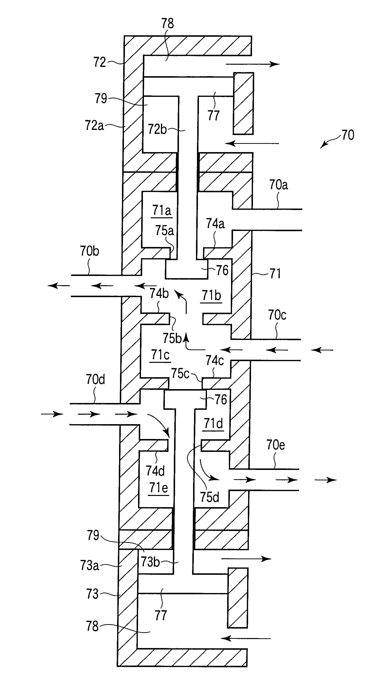
[0020]A five-port switch valve 70 according to the embodiment comprises a port 70c through which a high-pressure fluid is introduced, a chamber 71c which receives the fluid introduced through the port 70c, holes 75b and 75c formed in walls of the chamber 71c, a port 70b through which the high-pressure fluid flowing from the chamber 71c into the adjacent chamber 71c via the hole 75b is fed, a port 70d through which the high-pressure fluid flowing from the chamber 71c into the adjacent chamber 71d via the hole 75c is fed, two valve bodies 76 which independently open and close the two holes 75b and 75c, and two actuators 72 and 73 which alternately feed the high-pressure fluid via the ports 70b and 70d.

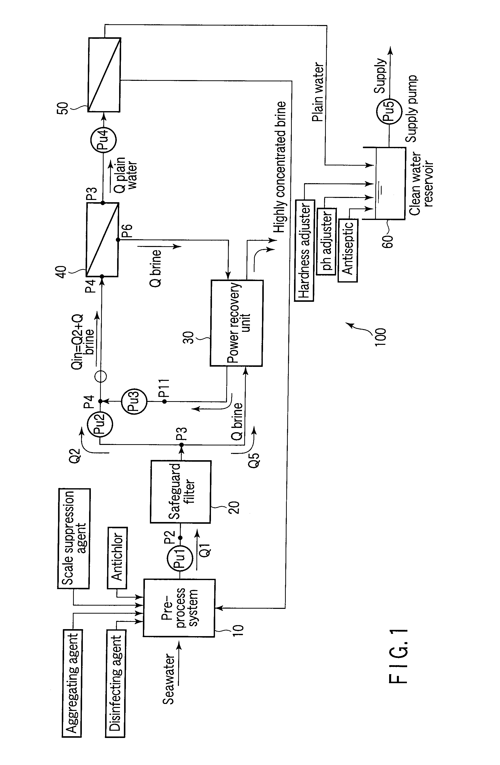
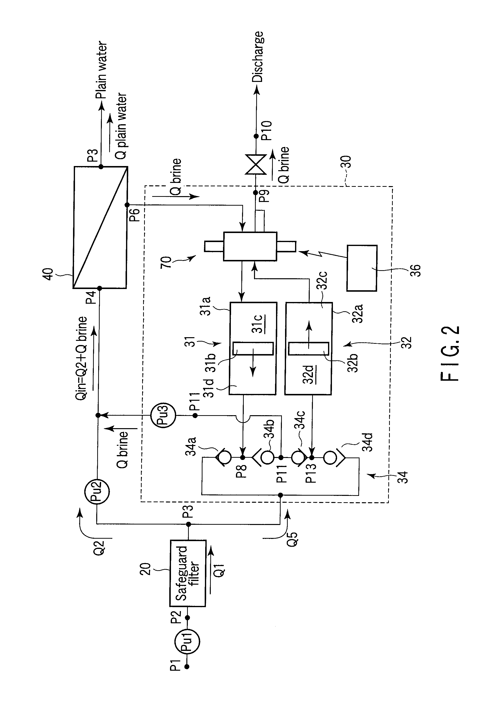
[0021]FIG. 1 is a schematic block diagram illustrating a seawater desalting plant 100 for converting seawater into plain water. As shown, in the seawater desalting plant 100, the drawn seawater i...


PUM


Abstract

A five-port switch valve includes a cylinder having five chambers defined by four partitions, and two actuators. The valve body of one actuator alternately opens and closes a hole formed in the partition and a hole formed in the partition. The valve body of the other actuator alternately opens and closes a hole formed in the partition and a hole formed in the partition. By virtue of this structure, brine fed into the central chamber through a port is alternately fed into two pressure converters through ports.

Description

CROSS-REFERENCE TO RELATED APPLICATIONS[0001]This application is based upon and claims the benefit of priority from prior Japanese Patent Application No. 2009-228638, filed Sep. 30, 2009, the entire contents of which are incorporated herein by reference.FIELD[0002]An embodiment described herein relates generally to a flow channel switching device for switching flow channels for water or oil etc.BACKGROUND[0003]Jpn. Pat. Appln. KOKAI Publication No. 9-52025 (hereinafter referred to as “Patent Document 1”), for example, discloses a reverse osmotic concentration apparatus that incorporates a switch valve as a flow channel switching device for switching flow channels for a high-pressure fluid. The reverse osmotic concentration apparatus is used as, for example, an apparatus for permitting seawater to pass through a reverse osmotic film and thereby be desalted.[0004]The switch valve disclosed in Patent Document 1 is switched by a to-be-concentrated liquid pressurized by a double-acting p...

Claims


Application Information

Patent Timeline
Patent Type & Authority Applications(United States)
IPC IPC(8): F16L37/34
CPCB01D61/20C02F2201/002C02F2103/08Y10T137/87949
Inventor NAGASHIMA, FUMIHIDETAKAHASHI, RYOICHIMATSUI, KOICHI
Owner KK TOSHIBA
Why Eureka
Try Eureka