Mold for molding light guide plate

A light guide plate and mold technology, applied in the field of molds, can solve the problems of large flow channel pressure loss, unreasonable flow channel design, slow molding speed, etc. Effect

Inactive Publication Date: 2015-04-01
东莞市现代精工实业有限公司
View PDF5 Cites 0 Cited by
  • Summary
  • Abstract
  • Description
  • Claims
  • Application Information

AI Technical Summary

Problems solved by technology

[0008] The technical problem to be solved in the present invention is to provide a molded light guide plate that overcomes the problems of unreasonable design of the flow channel of the mold for the existing molded light guide plate, large pressure loss in the flow channel, low yield rate, slow molding speed, and high manufacturing cost. the mold

Method used


Image

  • Mold for molding light guide plate
  • Mold for molding light guide plate

Examples


Embodiment 1

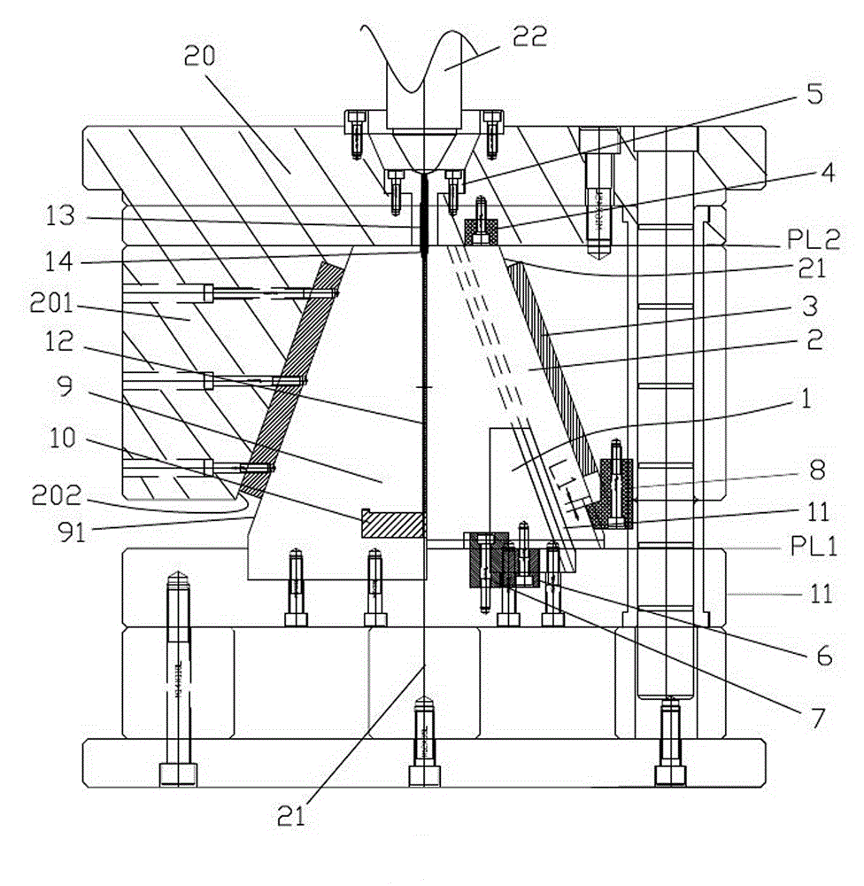
[0032] Embodiment 1, the mold of this embodiment is suitable for a horizontal injection molding machine.

[0033] Such as figure 1 As shown, a mold for forming a light guide plate includes a main flow channel 13 that feeds glue straightly. 14 connected.

[0034] Also include the front formwork 20 and the back formwork 11 that are arranged oppositely, the geometric center of the front formwork 20 plate surface and the geometric center of the back formwork 11 plate surface are called the center line 21 of this mould;

[0035] The left side of the geometric center on the front template 20 protrudes a front mold slope block 201 toward the rear template 11, and the front module slope 201 has a slope 202, and the slope 202 is located on the side close to the geometric center of the front template 20, And the angle between the slope 202 and the front template 20 is greater than 90 degrees on the side close to the centerline 21;

[0036] On the left side of the center line 21 on th...

Embodiment 2

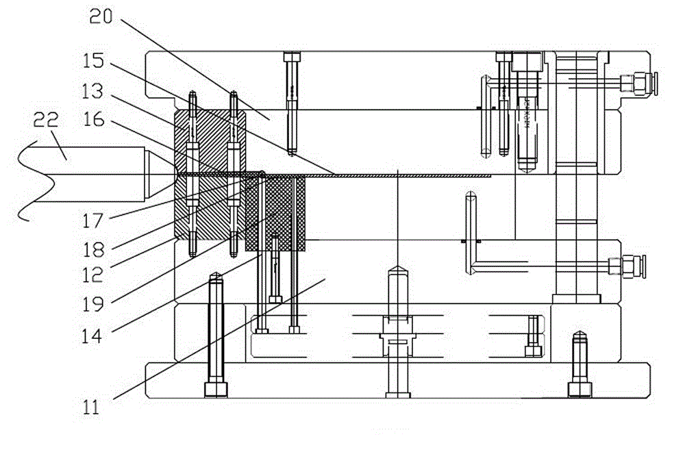
[0054] Embodiment 2, the mold of this embodiment is suitable for an angle injection molding machine.

[0055] Such as figure 2 As shown, a mold for forming a light guide plate includes a main flow channel 13 that feeds glue straightly. 14 connected.

[0056] Also include the front formwork 20 and the back formwork 11 that are arranged oppositely, the geometric center of the front formwork 20 plate surface and the geometric center of the back formwork 11 plate surface are called the center line 21 of this mould;

[0057] Install the first nozzle insert 15 on the front template 20, the first nozzle insert 15 is the front mold side forming the sprue 13, and fix the second nozzle at the position facing the first nozzle insert 15 on the back template 11 The insert 17 and the second nozzle insert 17 form the rear mold side of the sprue 13 , and the front mold side of the sprue 13 and the rear mold side of the sprue are closed to form the sprue 13 .

[0058] On the rear template ...


PUM


Abstract

The invention discloses a mold for molding a light guide plate, and relates to a mold technique. The mold comprises a main runner for charging glue straightly, a front mold plate and a rear mold plate; a glue charge end of the main runner is communicated with an injection nozzle of an injection molding machine; a glue discharge end of the main runner is communicated with a sprue of a mold cavity; the front mold plate and the rear mold plate are arranged oppositely. The main runner for charging glue straightly is adopted so as to form main runner straight ejection and branch runner straight ejection; the runner and the glue charge are smooth, the pressure loss in the runner is very low, and the glue charge speed is high, so that the molding speed is high, the yield is high, and the manufacture cost is reduced; meanwhile, because the pressure loss in the runner is very low, a high-power injection molding machine is not required to be adopted; on one hand, the energy consumption is reduced, the equipment investment can be reduced, and the production cost of a product is reduced further; according to calculation, the manufacture cost of the light guide plate can be reduced by about 5%, and the market competitiveness is improved.

Description

technical field [0001] The invention relates to a mold, in particular to a mold for forming a light guide plate. Background technique [0002] The light guide plate is a key component of the backlight source, and its function is to convert the point light source of the light-emitting diode (LED for short) into a surface light source with uniform light output. [0003] The light guide plate is a thin plastic sheet, which is injection molded. It is made with many grooves that change the path of light travel. At present, the area of ​​the light guide plate is generally relatively large, the length of which is more than 15 cm, the thickness is less than 1 mm, and the depth of the groove is 1-10 microns. For such a large-area, ultra-thin and shallow-groove light guide plate, the difficulty of injection molding can be imagined. [0004] The quality, molding speed, yield rate and manufacturing cost of the light guide plate are closely related to the mold, and the molding of the ...

Claims


Application Information

Patent Timeline
Patent Type & Authority Applications(China)
IPC IPC(8): B29C45/27B29C45/26
CPCB29C45/2708B29C45/2602
Inventor 何建明
Owner 东莞市现代精工实业有限公司
Why Eureka
Try Eureka