Treatment of aqueous liquid

Active Publication Date: 2011-03-31
MESSER IND USA INC
View PDF3 Cites 4 Cited by
  • Summary
  • Abstract
  • Description
  • Claims
  • Application Information

AI Technical Summary

Benefits of technology

[0020]Heat generated in the treatment is usually lost by evaporation to the atmosphere. The method and apparatus according to the present invention are advantageous in that for a given inflow of waste water to be treated, a relatively small volume treatment vessel containing a high concentration of bacterial solids can be utilised, thus keeping down evaporative heat loss from the surface of the liquid. It is possible to maintain the bulk of the liquid in the treatment vessel to temperatures between 20° C. and 80° C., i.e. abo

Problems solved by technology

So far to date, it has proved difficult to obtain the maximum benefit from tubular cross flow membrane filters in a waste water treatment process.
Difficulties arise in keeping the membrane's inner bore surfaces clean and therefore in exploiting their potential ability to handle hig

Method used


Image

  • Treatment of aqueous liquid
  • Treatment of aqueous liquid
  • Treatment of aqueous liquid

Examples


Embodiment Construction

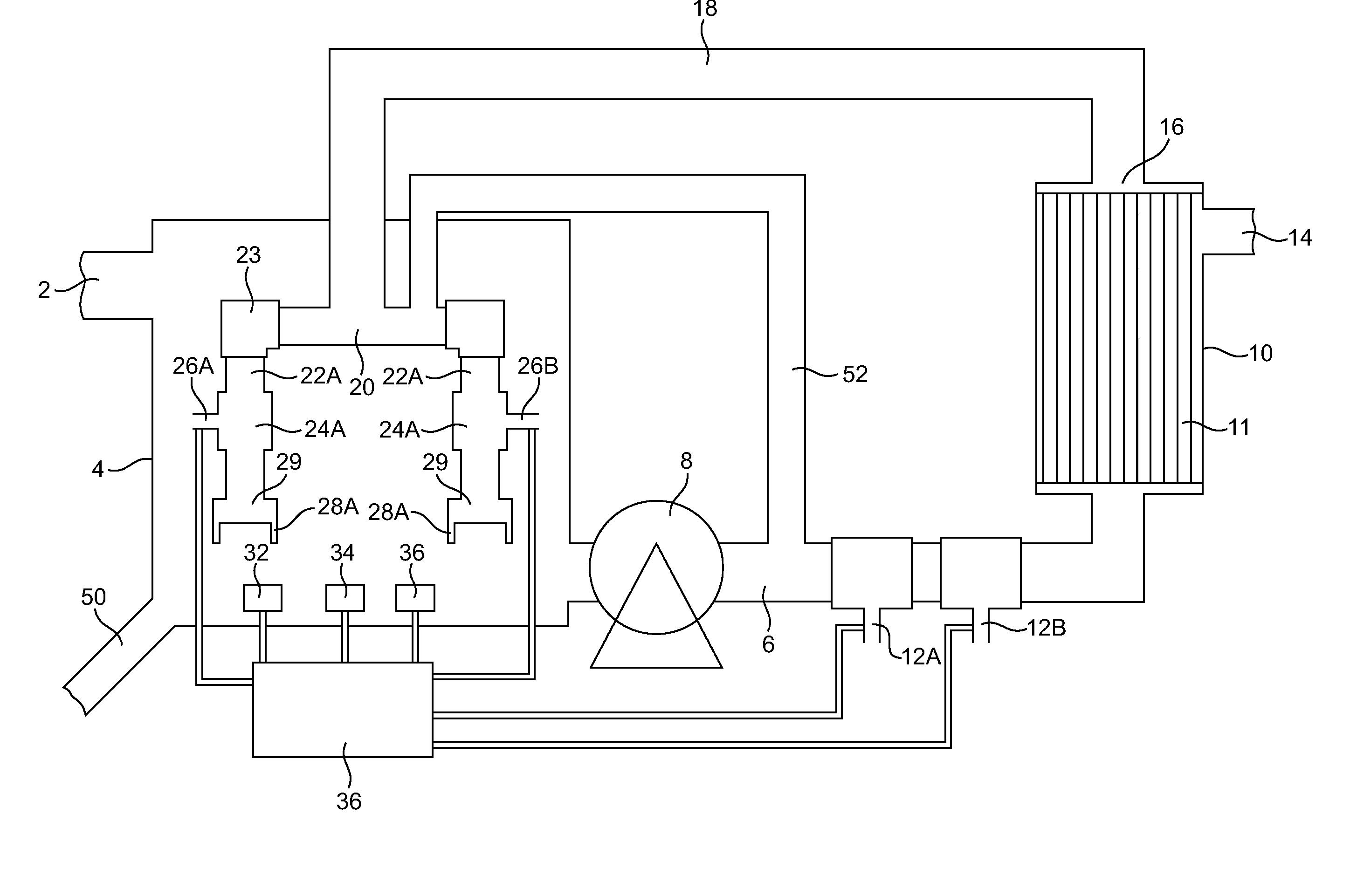
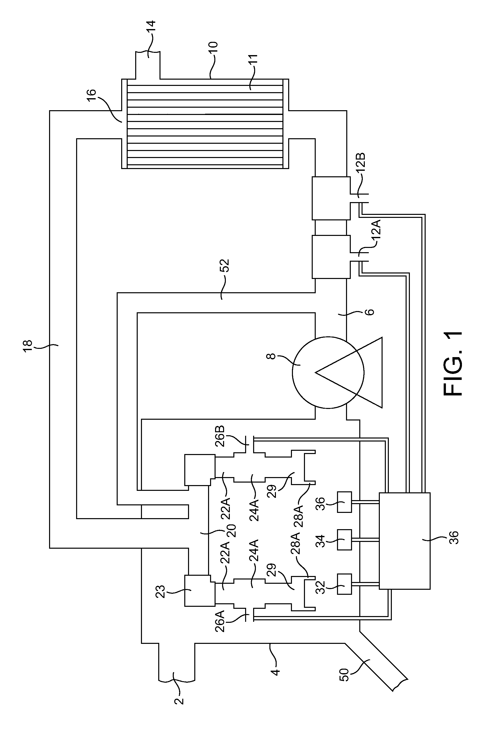
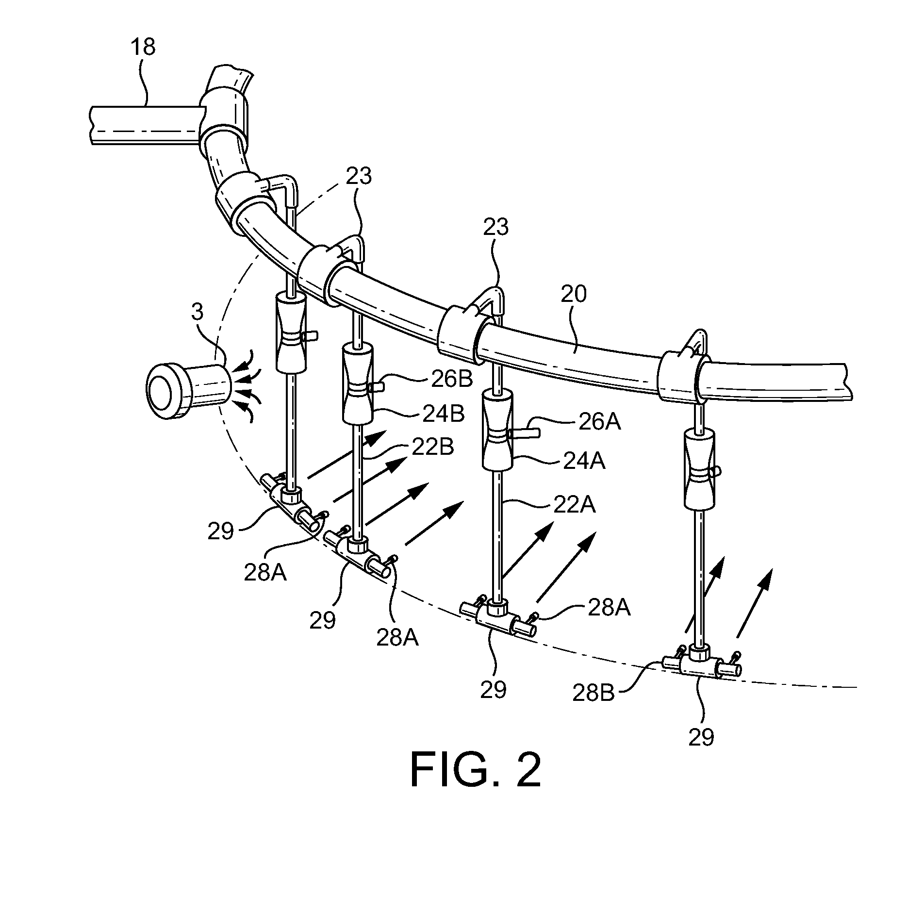
[0026]Like parts in different Figures are referred to below by the same reference numeral. The use of the Suffix A denotes an element particularly adapted for the introduction of oxygen and the Suffix B denotes an element particularly adapted for the introduction of air.

[0027]Referring to FIG. 1, a flow of aqueous liquid having a varying oxygen demand is conveyed continuously to an inlet 2 in the side of an open treatment vessel 4. The vessel 4 may be of any convenient capacity. Typically, it holds from 50 to 5000 m3 of liquid. Typically, the depth of the liquid in the vessel 4 is in the range 3 to 15 metres. The liquid can be, for example, domestic or industrial waste water having a BOD and / or a COD, the magnitude of the oxygen demand being dependent on the concentration and nature of the organic or chemical pollutants present therein. For example strong untreated domestic waste water may have a BOD of 400 mg / l and a COD of 1000 mg / l. The waste water typically contains aerobic bact...


PUM

PropertyMeasurementUnit
Timeaaaaaaaaaa
Acidityaaaaaaaaaa
Acidityaaaaaaaaaa

Abstract

Aqueous liquid having an oxygen demand flows into a treatment vessel where it is treated by suspended aerobic bacterial solids in the presence of dissolved oxygen. A pressurised flow of the treated liquid passes to a clarifying membrane separator effective to separate the flow into a discharge stream of clear liquid and a pressurised recycle stream concentrated in the aerobic bacterial solids. A first oxic gas is employed to scour the membranes and is conveyed away from the membrane separator in the pressurised recycle stream. The pressurised recycle stream is returned to under the surface of the liquid in the treatment vessel. A second oxic gas is introduced either into the pressurised recycle stream or into a further pressurised stream of aqueous liquid flowing into the same volume. The rate of introduction of the oxic gases is controlled with reference to the pH and dissolved oxygen concentration of the liquid in the vessel.

Description

BACKGROUND OF THE INVENTION[0001]This invention relates to a method and apparatus for the treatment of aqueous liquid having an oxygen demand.[0002]Conventional waste water treatment is carried out in a vessel by aerobic bacterial solids that degrade organic contaminants in the water in the presence of oxygen. The water in the vessel is agitated to keep the bacterial solids in suspension. Aeration of the water maintains the necessary aerobic conditions.[0003]On a conventional waste water treatment plant there is generally a continuous flow of water to be treated into the vessel and a continuous flow of treated water containing bacterial solids out of the vessel. The outward flow of treated water is directed from the treatment vessel to a settling tank in which the solids settle out under gravity, leaving a clear supernatant liquid that can be continuously discharged to the environment or for further treatment.[0004]It has been proposed to do away with settlement under gravity and em...

Claims


Application Information

Patent Timeline
IPC IPC(8): C02F3/12B01D65/02
CPCC02F3/1268Y02W10/10B01D65/02C02F3/12
Inventor HANSON, CEDRIC CHARLESPIGOTT, STUART MICHAEL
Owner MESSER IND USA INC
Why Eureka
Try Eureka