Joint and foldable structures employing the same

a foldable structure and joint technology, applied in the field of joints, can solve the problems of not being stackable compactable, not allowing a plurality of segments interconnected by such joints to stackably compact, etc., and achieve the effect of supporting significant weight and efficient compacting to a stowed configuration

Inactive Publication Date: 2011-03-31
ASHPOLE BENJAMIN C
View PDF105 Cites 21 Cited by
  • Summary
  • Abstract
  • Description
  • Claims
  • Application Information

AI Technical Summary

Benefits of technology

Therefore, a joint is desired wherein a series of substantially uniform segments interconnected by such a joint rotate in different, parallel planes and thus allow structures employing the same to efficiently compact to a stowed configuration and support significant weight.
The present invention is directed to joints, specifically, pivot joints comprising stop protrusions that rotatably fix the stop angle of substantially uniform segments interconnected by such pivot joints in respect to each other. A plurality of such segments, hereinafter referred to as brackets, interconnected by the joints, forms foldable extensions that are able to support significant weight in an extended configuration, and are also collapsible to a stowed configuration wherein the brackets are stackably aligned and directly adjacent to one another, limiting wasted space. The present invention is also directed to foldable structures, specifically foldable structures comprising foldable extensions described above and are thus able to collapse to a compact stowed configuration.
In yet another embodiment a support structure is provided, including at least one generally linear support member made up of a plurality of brackets, each bracket having a front end and a back end. The front end has a stop protrusion projecting from a side of the bracket and having a stop surface. The front end defines a front pivot point, the back end defines a back pivot point and a first edge surface. In the bracket, the front end of the first bracket is joined to the back end of the second bracket at the pivot points such that the brackets pivot relative to each other between a stowed position in which the first and second brackets are adjacent each other in generally parallel, aligned orientation, and an extended position in which the second bracket is extended linearly relative to the first bracket and the stop surface of the first bracket engages the edge surface of the second bracket. In the extended position, the joint withstands weight loads exerted on the edge surface.
In another example application, the present invention provides a foldable shovel comprising a handle shaft, a handle grip, and a shovel head. The handle shaft is comprised of at least one foldable extension, but preferably comprises at least two, which are removably attached such that the folding direction of each extension is in an opposing direction from the other, thus holding the handle shaft in a substantially rigid state and preventing buckling.

Problems solved by technology

However, a plurality of segments interconnected by such stop hinges would lie substantially on the same plane and thus not be stackably compactable, as the foldable ruler in FIG. 1a. FIG. 1c illustrates an example of a knuckle joint, which also stops the rotation of two segments interconnected by such joints in respect to each other.
Like the stop hinge in FIG. 1b, however, the knuckle joint in FIG. 1c does not allow a plurality of segments interconnected by such joints to stackably compact as in the foldable ruler in FIG. 1a.

Method used


Image

  • Joint and foldable structures employing the same
  • Joint and foldable structures employing the same
  • Joint and foldable structures employing the same

Examples


foldable table example

Application

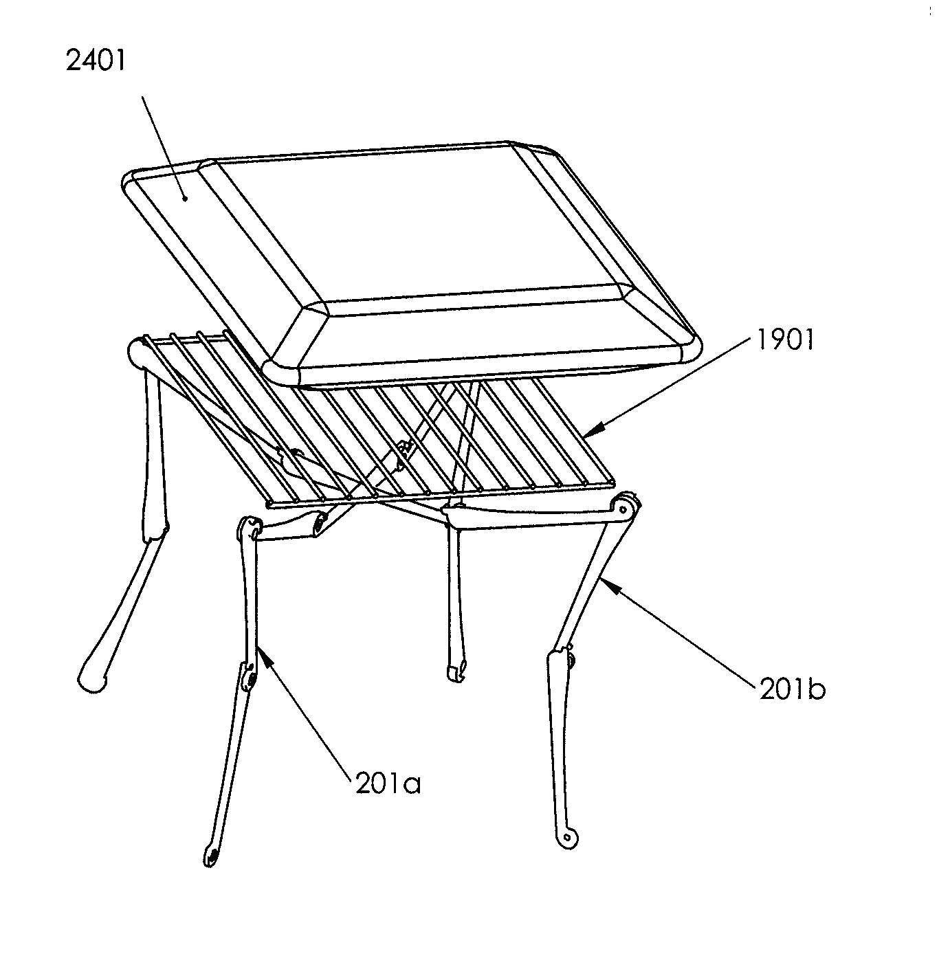
FIGS. 22a-22c illustrate another application of the foldable joint 101 mechanism, which is a table in this example application but a similar assembly may alternatively be applied to other types of furniture, such as sofas, nightstands, seating devices, as described below, and many others. The table example includes at least two foldable extensions 201a and 201b that intersect in approximately the center to form a support structure 1801 to which a table top 2201 is removably attached. Those of skill in the art will recognize that the support structure 1801 of the table is constructed similarly to that of the grill application described above. Similarly to the support structure 1801 of the grill, the foldable extensions 201a and 201b of the table interconnect through complementary assembly notches 1802, one on the bottom surface 305 of the first frame element 201b, and another on the top surface 304 of the second frame element. The foldable extensions of the support structu...

example application

Shovel Handle Example Application

FIG. 28a illustrates a foldable shovel that comprises at least one foldable extension to form the handle shaft 3202, removably attached to the shovel blade 3201 at one end and a handle grip 3203 at the other end. While the handle shaft 3202 may be formed out of one foldable extension 201, FIGS. 28b-28c illustrate how at least two foldable extensions 201j and 201k may be connected such that they fold in opposite directions and thus maintain one another in the extended configuration. FIG. 28d is a detailed view of how foldable extensions 201j and 201k may be interconnected and folded into a compact stowed configuration. The handle grip 3203 and shovel blade 3201 are detachable for shipping, storage, and user transportation. This doubling configuration may be employed in other types of handles or devices with elongated sections, such as fishing rods, ski poles, oars, swords, javelins, rackets, bats, basketball hoops, shelter frames poles, walkers, canes...


PUM


Abstract

A folding joint mechanism for stackably collapsing elongated structural sections includes a plurality of substantially identical brackets pivotably interconnected and rotatable between an extended and a stowed configuration. In the extended configuration, the brackets abut each other against stop protrusions on the top outside surface of each bracket forming foldable extensions that are able to support significant weight by distributing the top-side force. In the stowed configuration, the brackets are compacted to a substantially stacked disposition whereby the brackets are aligned and directly adjacent to one another. The joint and bracket assemblies may be employed in elongated sections of various structures in which compactability may be advantageous for shipping, storage, and user transportation.

Description

RELATED APPLICATIONThe present application claims priority under 35 USC 119(e) from US Provisional Application No. 61,245,757 filed Sep. 25, 2009.BACKGROUNDThis application relates to joints, specifically joints that allow for segments connected by such joints to support significant weight, as well as to compact efficiently to a stowed configuration, facilitating shipping, storage, and user transport of structures constructed of the same.Methods of compacting various structures have been known for some time and are very useful for disassembling components of large volume structures to be stowed and transported with much lower volume. Yet, all of these have serious drawbacks that reduce compactability, functionality, and convenience. Telescoping mechanisms, for example, are employed to stow and transport elongated objects such as tripods, projector stands, antennas, seat height adjusters, and the like. These telescoping structures, however, often rely on the friction of the segments ...

Claims


Application Information

Patent Timeline
Patent Type & Authority Applications(United States)
IPC IPC(8): F16M11/00F16B1/00
CPCA47C4/20Y10T403/32409A47C19/12A47J37/0694A47J37/07E04G1/34E04G5/08E04H15/48F16M11/38A47J37/067F16M11/22F16M11/24F16M2200/044F16M2200/065A47J2037/0777A47J37/0763Y10T403/32393Y10T403/32401A47C19/021
Inventor ASHPOLE, BENJAMIN C.
Owner ASHPOLE BENJAMIN C
Why Eureka
Try Eureka