Multi-phase rotary machine control apparatus and electric power steering system using the same

a control apparatus and multi-phase technology, applied in the direction of electric generator control, dynamo-electric converter control, dynamo-electric gear control, etc., can solve the problems of short circuit, increased power output of normal power supply sources for compensation, and same problems, so as to minimize the reduction of the output power of an inverter

Active Publication Date: 2011-03-31
DENSO CORP
View PDF4 Cites 48 Cited by
  • Summary
  • Abstract
  • Description
  • Claims
  • Application Information

AI Technical Summary

Benefits of technology

[0011]It is therefore an object of the present invention to minimize reduction of output power of an inverter even if a failure arises in a switching element.

Problems solved by technology

Thus, the period, in which the normal power supply sources are allowed to output increased power for compensation, is limited to be short.
If the off-failure arises, the same problem arises as in the patent document 2.

Method used


Image

  • Multi-phase rotary machine control apparatus and electric power steering system using the same
  • Multi-phase rotary machine control apparatus and electric power steering system using the same
  • Multi-phase rotary machine control apparatus and electric power steering system using the same

Examples


first embodiment

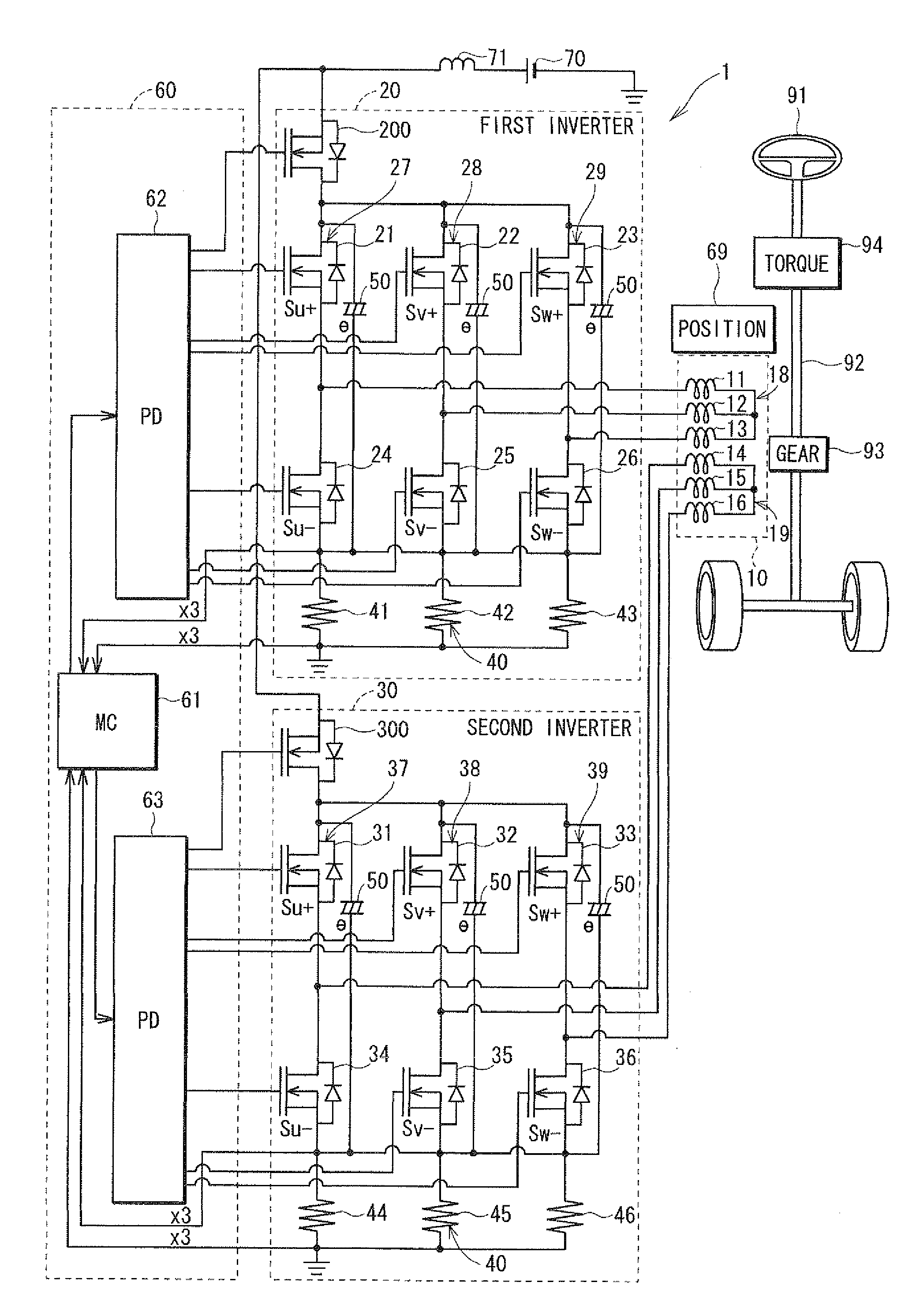
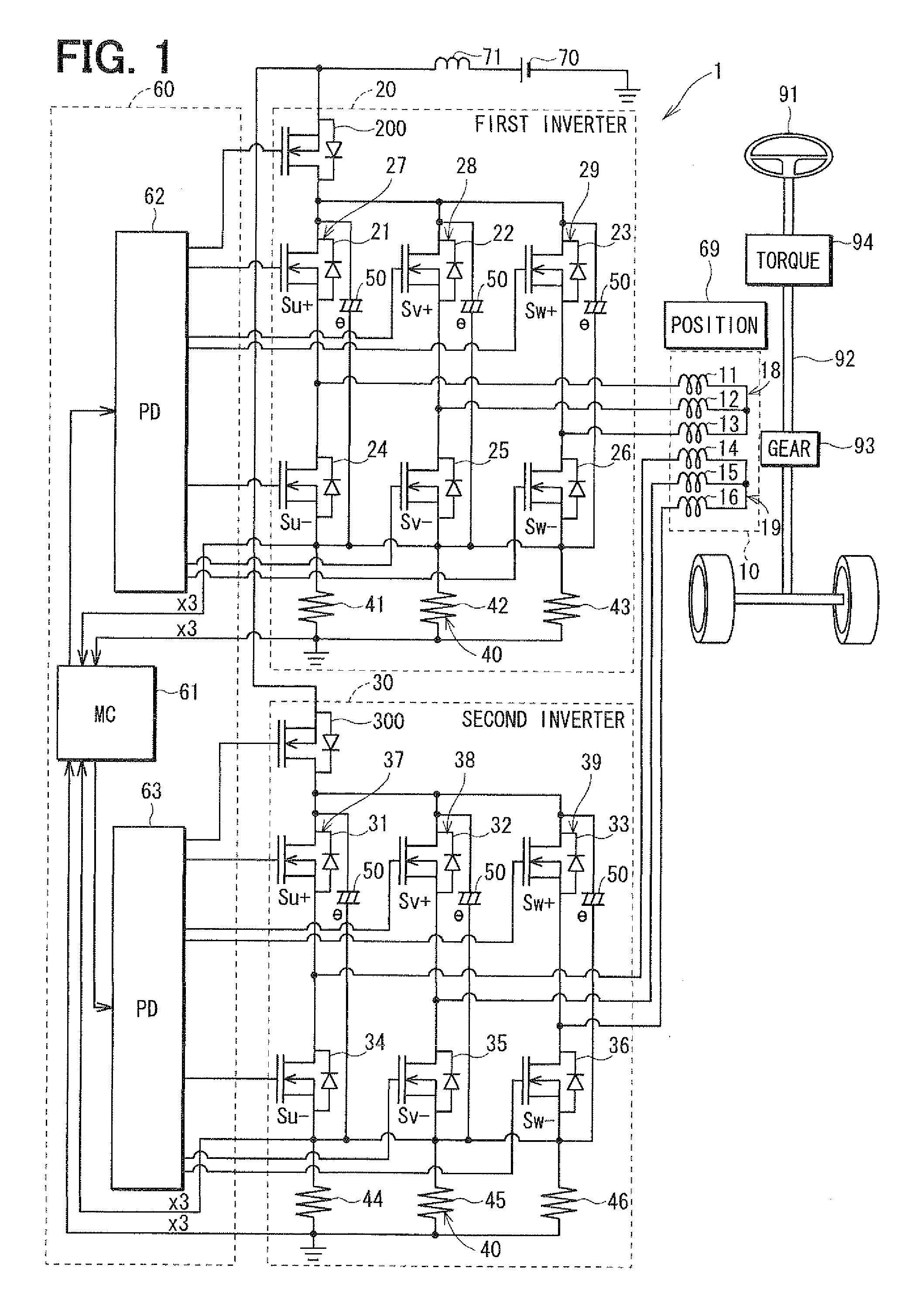
[0023]Referring first to FIG. 1, a multi-phase motor control apparatus 1 is provided for controlling the operation of a multi-phase electric motor 10, which is a rotary machine. The motor 10 is used in an electric power steering system (EPS) for power-assisting the steering operation of a vehicle. The motor 10 drives a column shaft 92, which is a rotation shaft of a steering wheel 91 of the vehicle, through a gear 93 to generate a rotation torque so that the steering operation of the steering wheel 91 is assisted. More specifically, when the steering wheel 91 is operated by a driver of the vehicle, a steering torque generated by the column shaft 92 is detected by a torque sensor 94. A vehicle speed is detected by a speed sensor (not shown) and acquired through a controller-area-network (CAN, not shown). The motor 10 is controlled in accordance with the detected torque and the detected vehicle speed.

[0024]The motor 10 is a three-phase brushless motor, which drives the gear 93 in the ...

second embodiment

[0065]According to the second embodiment, the multi-phase motor control apparatus 1 is configured similarly as in the first embodiment. However, the control part 60 is configured to perform the failure-time control as shown in FIG. 6.

[0066]In FIG. 6, the failure-time control is shown with respect to the off-failure of the U1 low-side FET 24 in the first inverter 20 as an example. The three-phase currents Iu1, Iv1, Iw1 supplied to the first coil set 18 and the generated torque Tq1 are the same as FIG. 4B. In the first embodiment, as shown in FIG. 5, the total torque Tq3 decreases at two electric angles in correspondence to the decrease of torque Tq1 in the first coil set 18. In the second embodiment, therefore, the second inverter part 30 is also controlled to compensate for the torque decrease in the first coil set 18.

[0067]According to the second embodiment, a torque difference between two torques is calculated. One torque is generated when the first inverter part 20 is controlled ...


PUM


Abstract

A failure identification part identifies a switching element pair having off-failure, in which a FET of the switching element pair in a first inverter part is disabled to turn on. A failure-time control part controls other switching element pairs and of the first inverter part based on failure-time phase current command values calculated as a function of a rotation position and a q-axis current command value. The failure-time control part controls a second inverter part normally. A motor is persistently driven with the minimum reduction in motor torque, even when the FET fails.

Description

CROSS REFERENCE TO RELATED APPLICATION[0001]This application is based on and incorporates herein by reference Japanese patent application No. 2009-227684 filed on Sep. 30, 2009.FIELD OF THE INVENTION[0002]The present invention relates to a multi-phase rotary machine control apparatus and an electric power steering system using the same.BACKGROUND OF THE INVENTION[0003]A conventional a multi-phase rotary machine control apparatus controls a multi-phase rotary machine by switching on and off a plurality of switching elements. It is proposed by the following patent documents to drive a rotary machine to maintain its rotation even if a part of a plurality of switching elements fails.[0004]Patent document 1: JP 2005-304119A[0005]Patent document 2: JP 6-98596A[0006]Patent document 3: JP 2009-6963A (US 2010 / 0017063 A1)[0007]According to patent document 1, a plurality of electric power supply sources such as inverters is provided. If any one of the power supply sources fails to operate norm...

Claims


Application Information

Patent Timeline
Patent Type & Authority Applications(United States)
IPC IPC(8): H02H7/08B62D5/04B62D6/00B62D119/00H02P21/00H02P27/04
CPCB62D5/0463H02P29/022B62D5/0487B62D5/0484H02P29/032
Inventor MUKAI, YASUHIKO
Owner DENSO CORP
Why Eureka
Try Eureka